Learn to Sketch: Part 4
“In this article, I describe three enhancements that can be added to your sketches to make them more useful when sharing your ideas with others and more interesting in general. They are Motion Arrows, Annotations, and Dimensions. ”
Motion Arrows
As engineers, we’re often designing things that move or that have movement associated with them. Motion arrows are the primary mechanism for conveying this movement. For example, if I am designing a pepper mill, I might sketch the mill’s geometry, then sketch the motion arrows to indicate the relative movement between the parts, as shown below.

Motion arrows can be added to two dimensional or three dimensional sketches. When working in three dimensions, arrows can be added to flat planes, cylindrical surfaces, or otherwise curved surfaces.
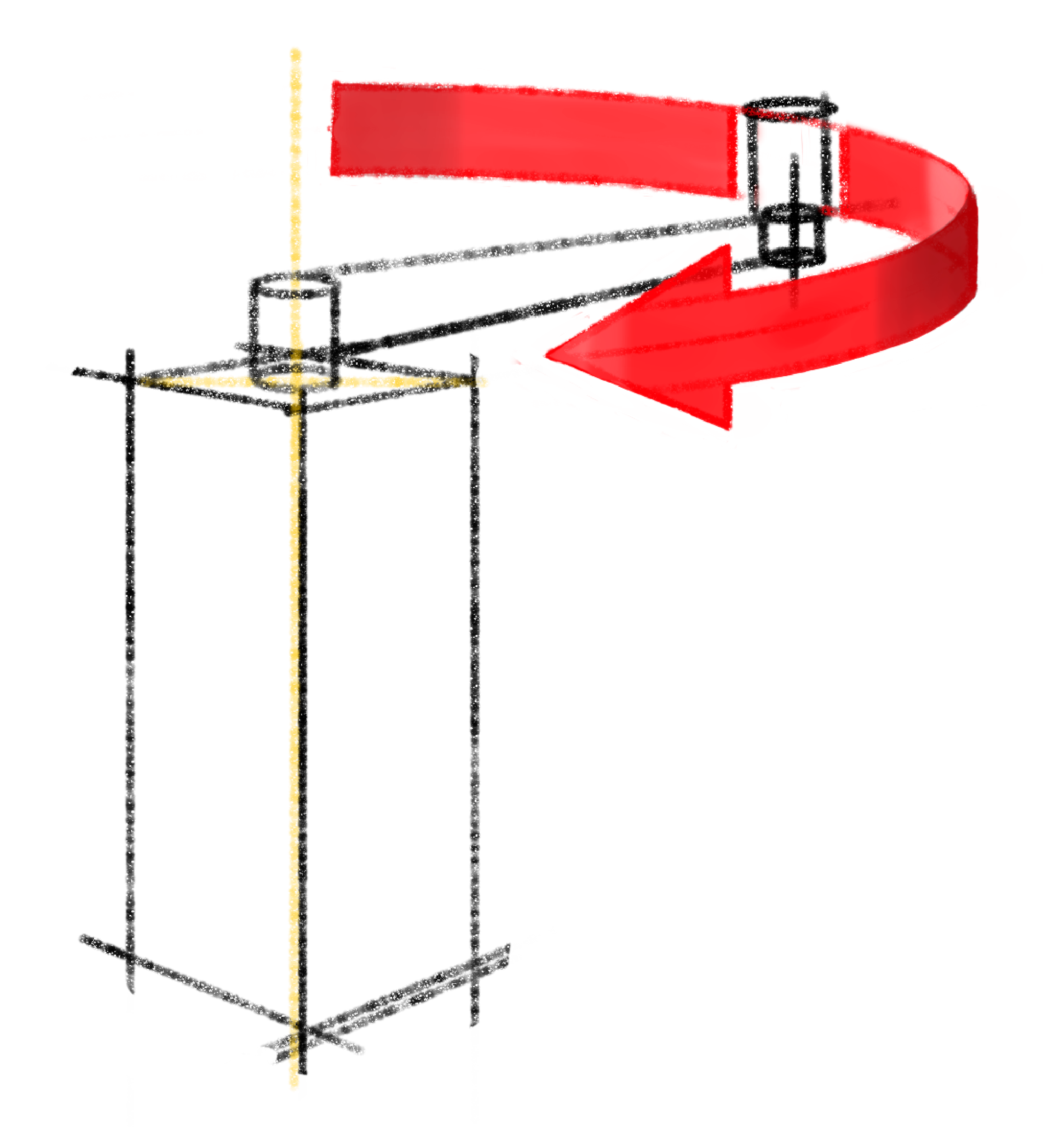
When adding motion arrows to flat planes, be thoughtful about what plane you want the arrow to appear on. For example, in the sketch below, I have put the horizontal part of the arrow closer to the object then I did for the vertical part of the arrow -- to illustrate how the placement matters.
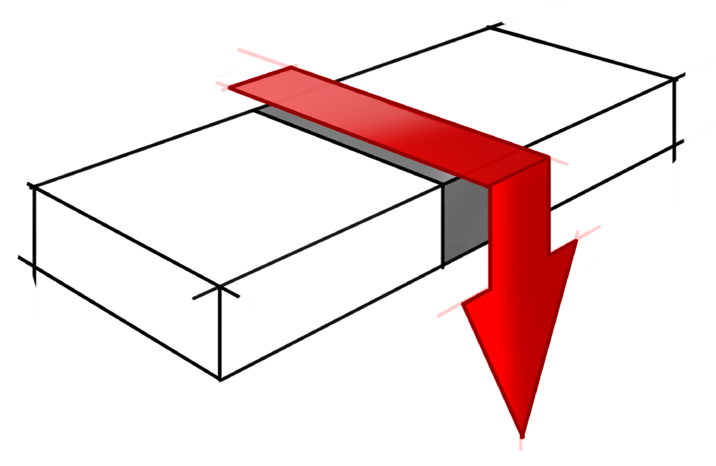
It is important to note that sketching these arrows is like sketching any geometry on the part – all the geometric laws apply. All lines converge to the vanishing points, and all vertical lines are perfectly vertical, and so on.
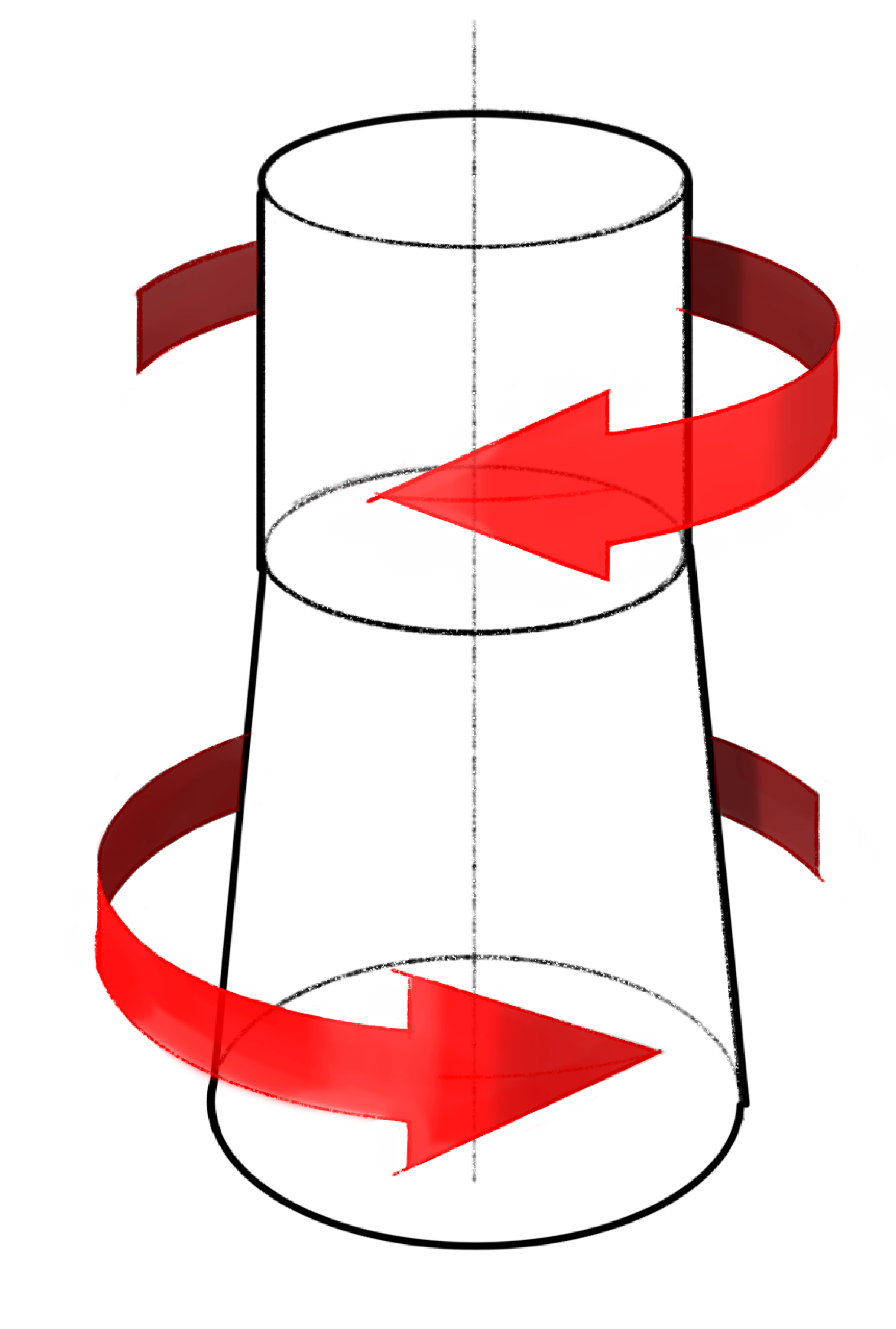
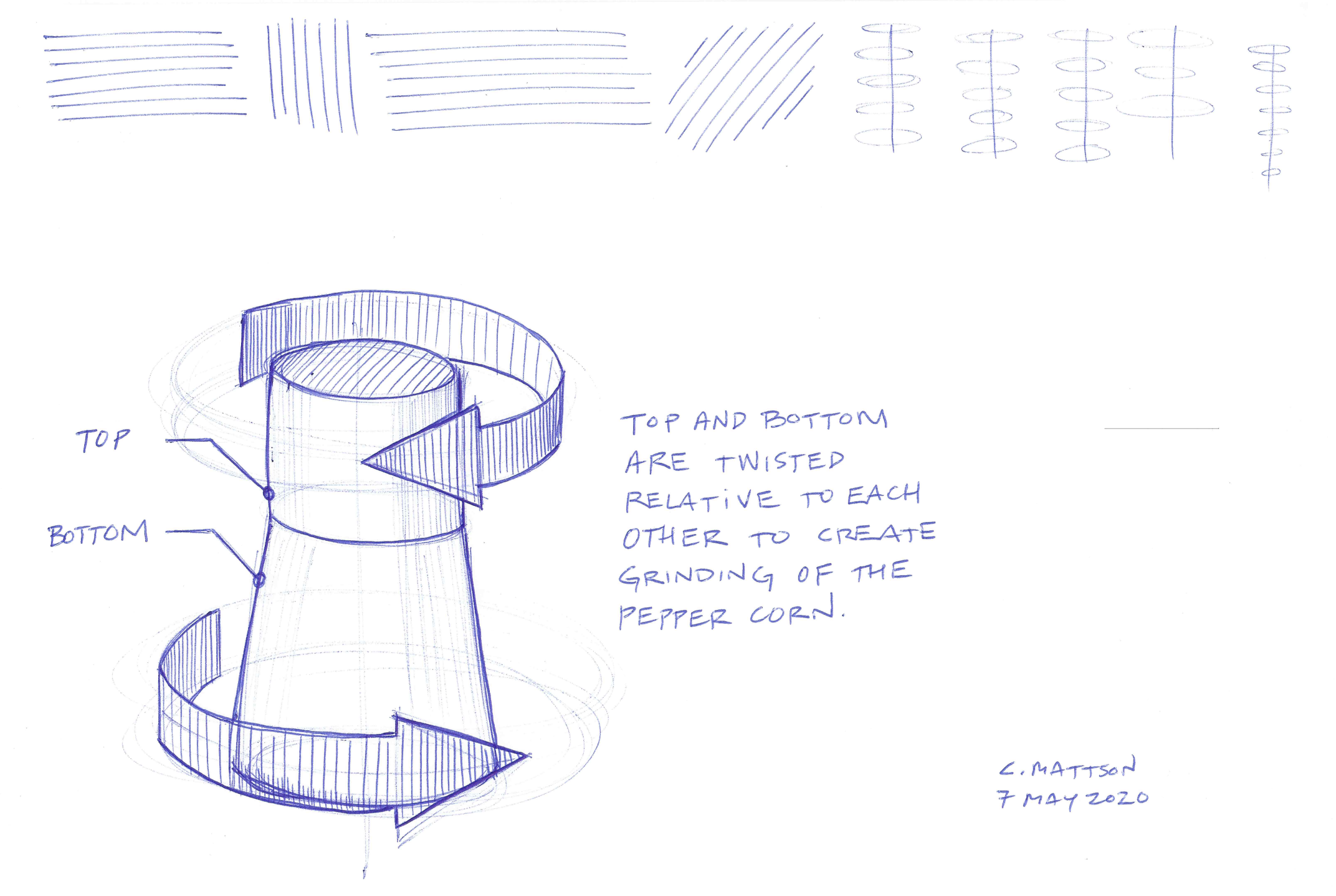
The same is true when making arrows on cylindrical surfaces. If you want to convey a twisting motion, remember that a circular twisting will be shown as an ellipse when drawing in two-point perspective. To sketch this kind of arrow, first make or identify the axis of rotation (shown as a long vertical line below). Then sketch three evenly spaced concentric ellipses around that axis. The top ellipse defines the top of the arrow body, the middle ellipse defines that tip location, and the bottom ellipse defines the bottom of the arrow. Next, draw two vertical lines; the one that represents the end of the tail, and the other that defines the broad end of the arrow head. Finish the geometry of the arrow by drawing the two diagonal lines from the tip to the broad end.
Shading your arrows gives them depth, makes them more interesting, and sometimes easier to understand. Imagine a light source (I typically put my light sources to the left and above my object, and in the foreground). Once you have placed a light source, think about where the arrow would be light and where it would be dark. When I sketched the arrow above, I used my iPad, the Apple Pencil, and the Sketch Book Pro App. I made a solid arrow, then added dark patches and light patches to give it depth. When I sketched the arrow below, I shaded it with vertical lines, and simply decreased the spacing between lines where it needed to appear dark, and increased it where it needed to appear light.
A common way to convey a dynamic loading or more dynamic movement is to use the kind of arrow shown below. Note the tail of the arrow.

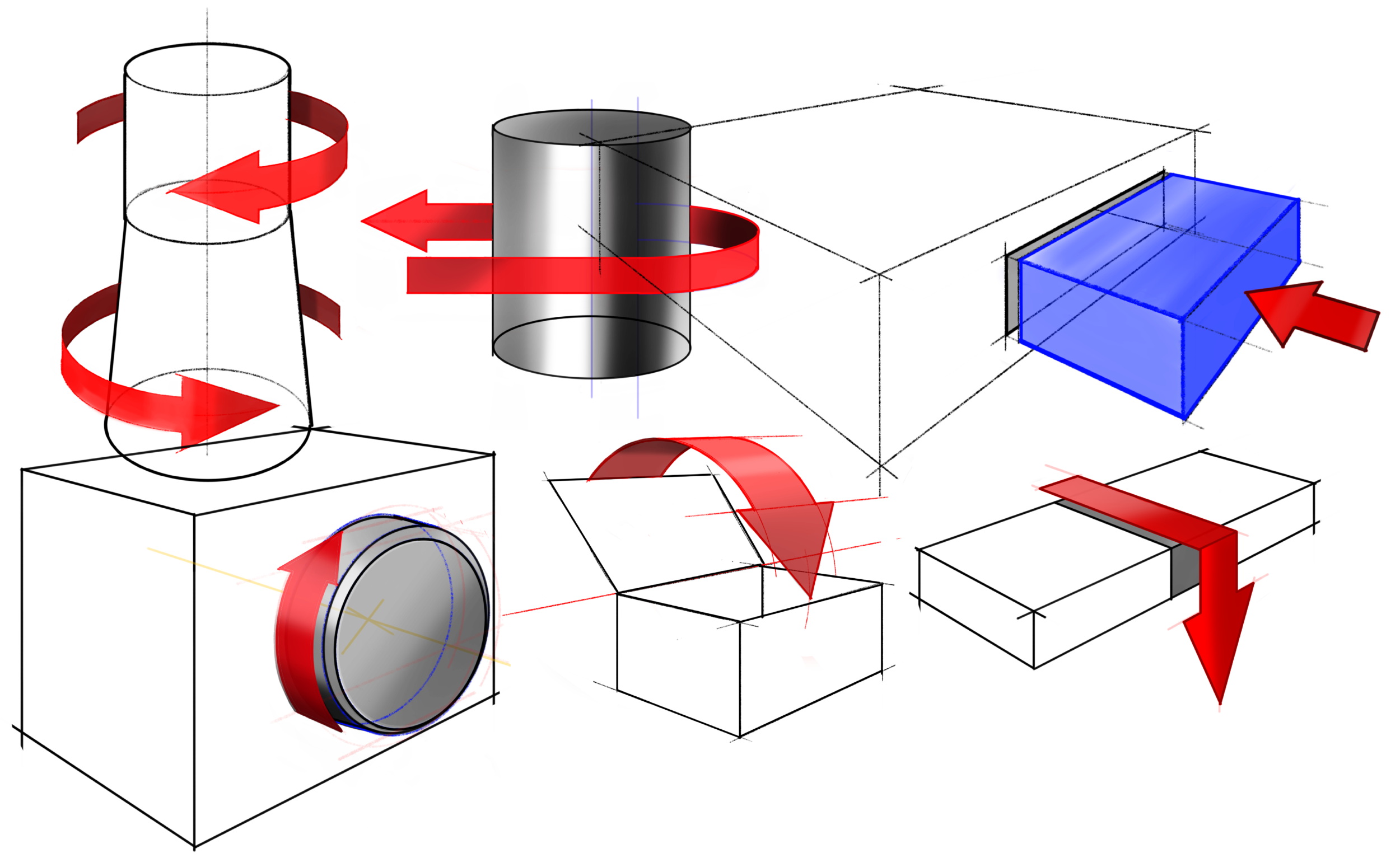
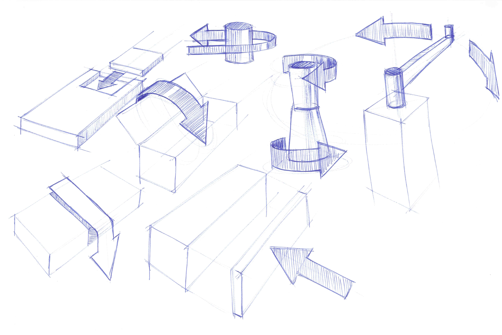
There are a large variety of motions that can be conveyed with motion arrows including the following:
Two objects meeting.

One object placed on another. Notice the arrow is sketched as sitting up, as opposed to laying down as shown in the next sketch. Either orientation would do in this case.

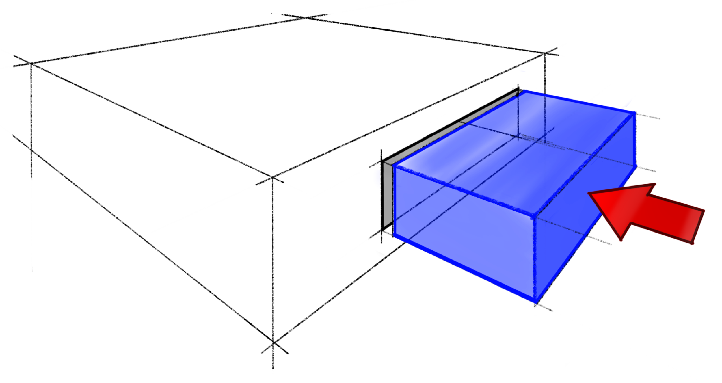
One object inserted into or extracted from another. Notice the arrow is sketched as laying down, as opposed to sitting up as shown in the previous sketch. Either orientation would do in this case.
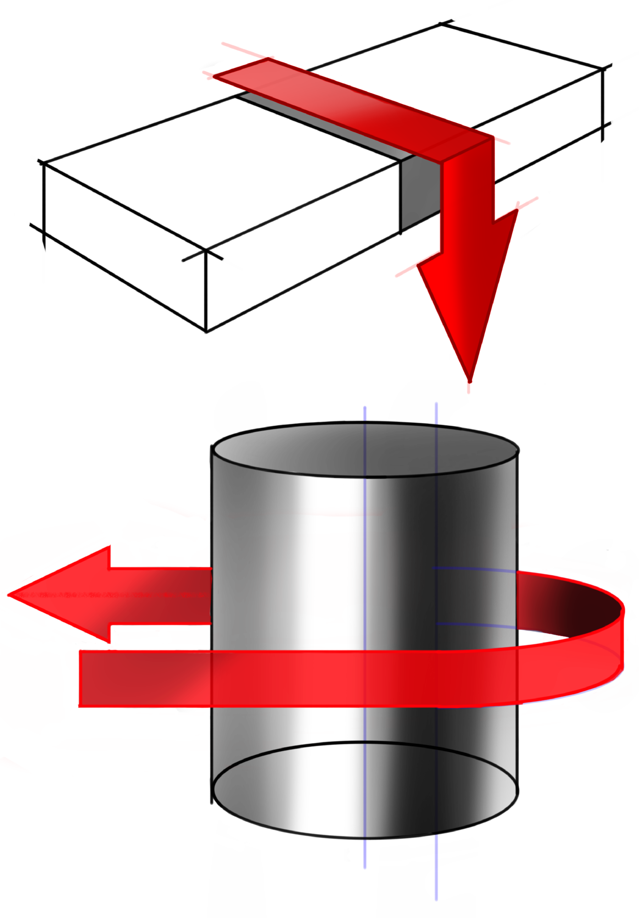
Movement around an object. In the cylindrical sketch, notice that the center of the cylindrical portion of the arrow is the blue line sketched to the right of the cylinder’s center.
Movement around a hinge. Notice the construction lines that help me know where the head of the arrow should be.

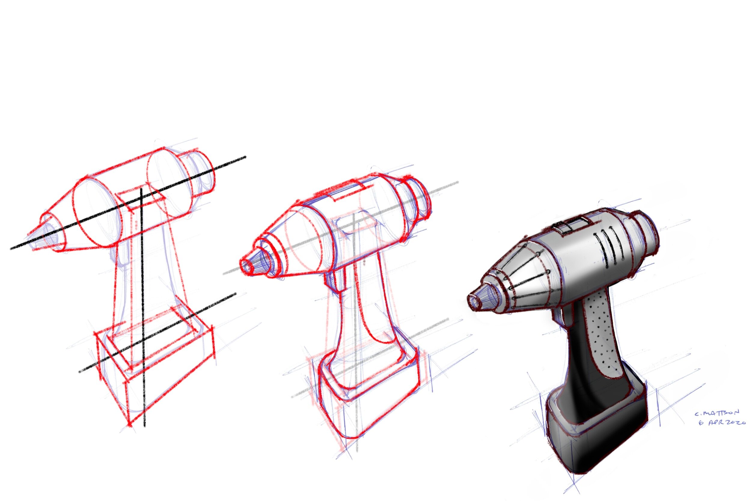
Turning a knob. Notice the arrow on the closer knob is drawn on a cylindrical surface, while the knob further away has motion arrows drawn on a plane.

Twist an object. Notice the lower arrow is drawn as a more open ellipse, just as the bottom of the object is drawn as a more open ellipse compared to the top.
Crank the handle of an object. Notice the center of the cranking motion is the yellow axis, just as it would be in real life.
Movement through an object. Notice how the arrow converges to the vanishing points in both directions.

The most important thing to observe from the sketches above is that all of them are drawn using the same geometric principles/rules/math that we use when making the geometry of the part. Keeping that in mind and practicing, is what will lead to hand sketches that convey your message of movement more clearly.
Annotations
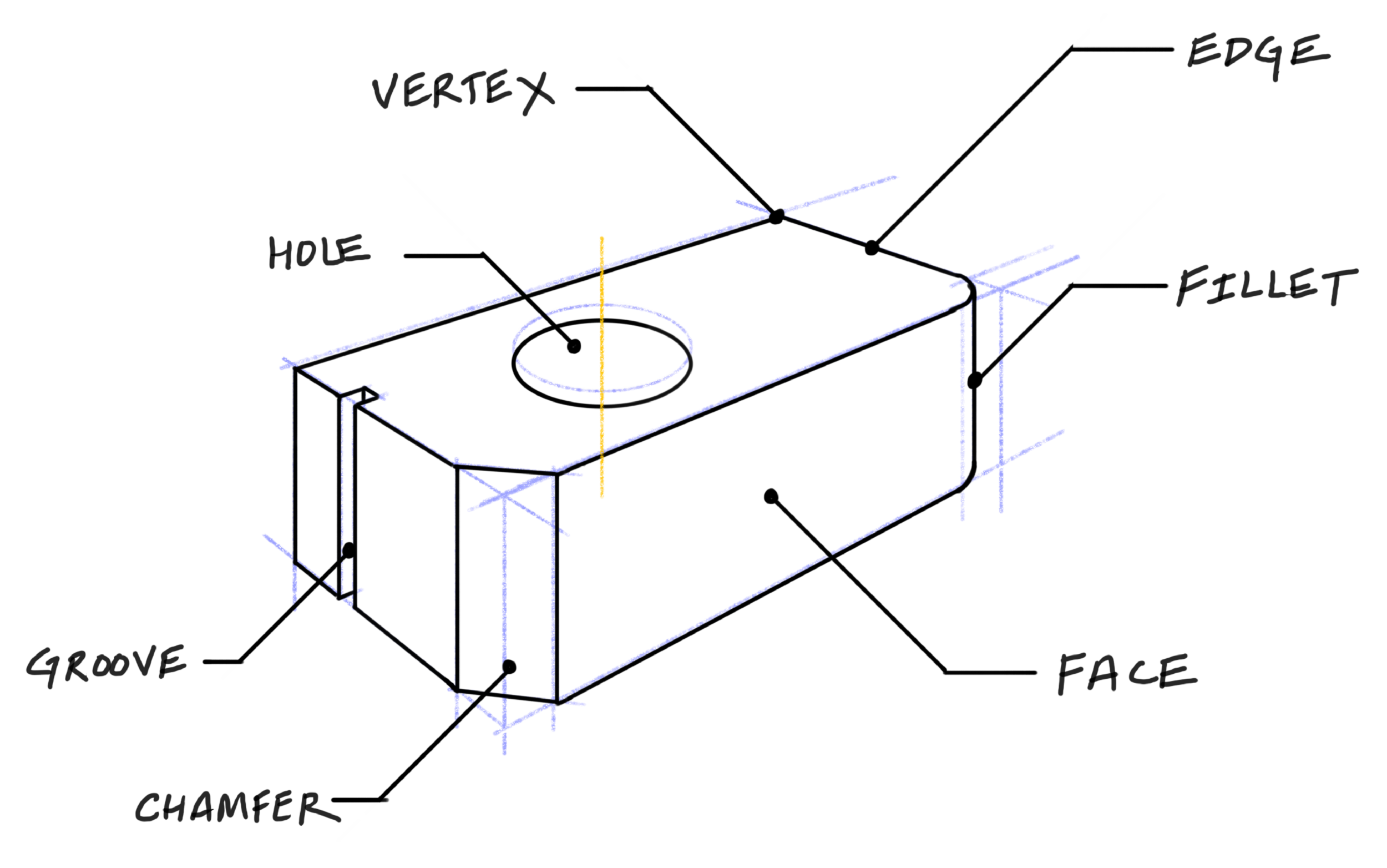
Sketches can be made even more valuable by adding a small amount of text to the sketch. These annotated sketches are valuable when they convey or clarify the sketch. For a clean looking annotated sketch, generally do the following:
Write your text horizontally and at the same height throughout.
Use two-part leader lines where the line closest to the object is 45 degrees and the part closest to the text is horizontal.
Use leader lines with dots touching the feature you are annotating. You can also use leader lines with arrows pointing to the feature, though I reserve the arrows for dimension lines.
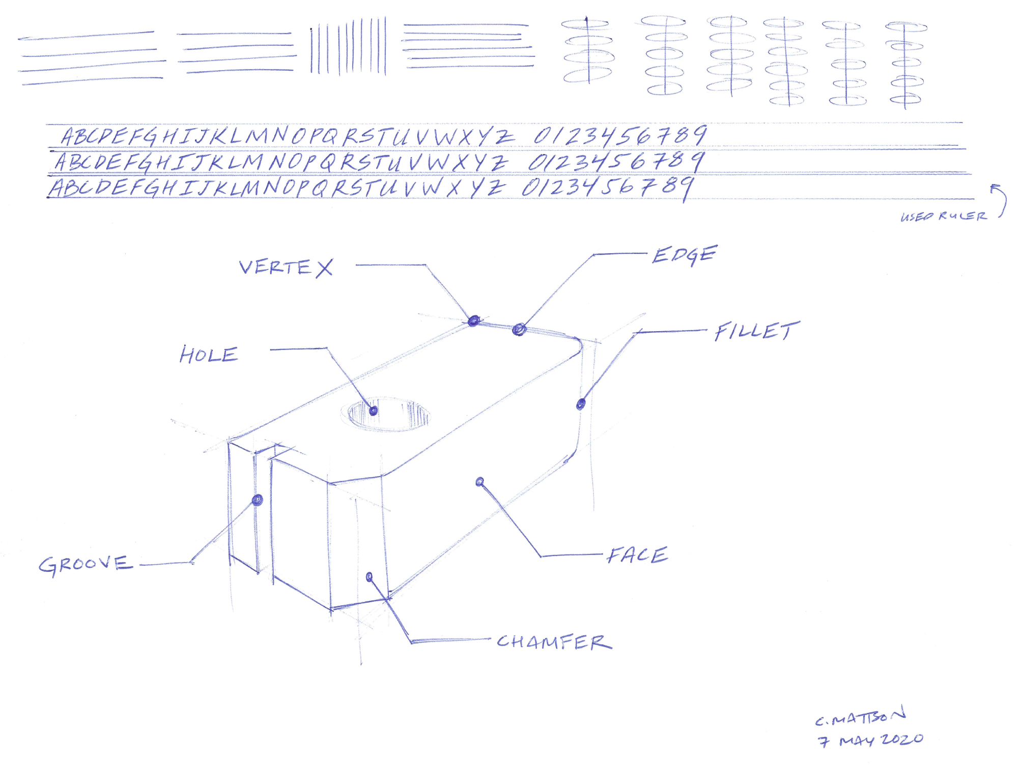
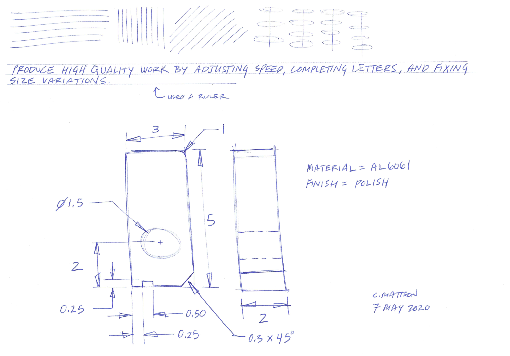
To produce useful annotations, your lettering needs to be readable. Traditionally, hand drawings in engineering use only capital letters. Whether or not you choose to follow this tradition, you’ll likely need to practice your lettering. Look at the differences between the two practices I did.

To get better results, slow down and treat each letter as having a correct geometry that needs to be made. That geometry includes consistent sizing (height). If it helps, sketch some lines to stay within and use them to achieve consistency. Finally, make sure that letters are complete and not running into adjacent ones. For example, look at the E’s from my better versus my worse set. Some of the E’s in the worse set are incomplete.
Above all, remember that your lettering should enhance your message, not distract from it.
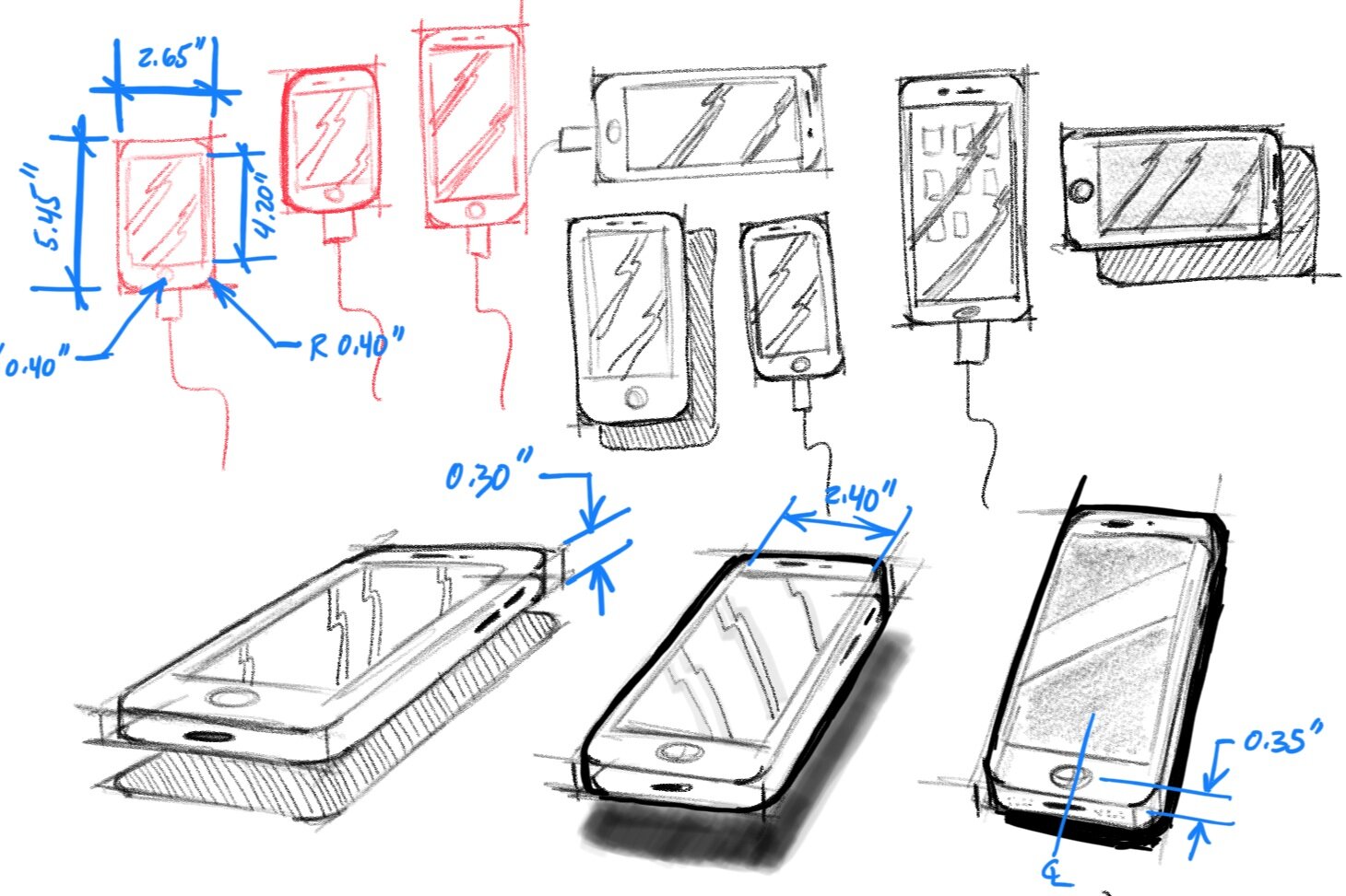
Dimensioned Sketches
Adding dimensions to our sketches is a logical enhancement that helps convey basic sizes and prepares us for more detailed parts of the product development process.

It is useful to remember that hand sketches are not for production purposes, so these hand sketches do not necessarily need to conform to technical drawing standards. Specifically, it is ok for a hand sketch to not be fully dimensioned (because you are only conveying a concept!). Further, the precision of dimensions does not necessarily need to be high.
To produce good hand-sketched dimensions generally do the following:
When dimension lines for circles, arcs, and chamfers, use two-part leader lines where the line closest to the object is 45 degrees, and the part closest to the text is horizontal.
Draw leader lines and dimension lines for circles and arcs such that the leader line would extend through the center of the circle or arc.
Use arrows heads that are three times longer than they are wide. These will look more natural because those are the ratios used in technical drawings.
Sketching Exercises
As you do the following exercises, think about arrows and letters as geometric objects in your sketch. Use basic geometric rules to create them, such as adhering to vanishing points and more. Note that the numbering of this list is continued from Part 3 of this series.
10. Annotation Exercise
a) Warm up for one minute by drawing straight lines and ellipses in the top fifth of the paper.
b) Spend three minutes writing the alphabet and 0-9 numbers. Practice consistent height in horizontal lines.
c) Spend 2 minutes sketching an object (without annotations) similar to the one shown in the Annotations section above.
d) Spend 4 minutes annotating the object from (c).
11. Motion Arrow Exercise
a) Warm up for one minute by drawing straight lines and ellipses in the top fifth of the paper.
b) Choose a motion (twist, around, insert, etc.) and sketch an object that will be exposed to that motion. Sketch a basic representation of the object, so you can spend your time sketching the motion arrows. Spend roughly 3 minutes on this.
c) Use roughly 4 minutes sketching the motion arrow(s).
d) Spend 2 minutes adding text (as an annotation) to the sketch.
Other motion arrows.
12. Dimensioning Exercise
a) Warm up for one minute by drawing straight lines and ellipses in the top fifth of the paper.
b) Spend an additional minute doing a lettering warm-up. Write the alphabet or some other useful sentence like: Produce high quality work by adjusting speed, completing letters, and fixing size variations. This covers every letter, and is a useful reminder.
c) Spend 2 minutes drawing a two dimensional view(s) of an object such as the one shown in the Annotations sections above.
d) Spend the remaining time (6 minutes) adding dimensions and annotations to your sketch.
Try this exercise routine to build skills related to motion arrows, annotations, and dimensioned sketches.
Exercise Routine 4
Day 1: Do the Annotation Exercise
Day 2: Do the Motion Exercise for two objects meeting (see Motion Arrows section).
Day 3: Do the Motion Exercise for one object inserted into or extracted from another.
Day 4: Do the Motion Exercise for movement around an object.
Day 5: Do the Motion Exercise for movement around a hinge.
Day 6: Do the Motion Exercise for turning a knob.
Day 7: Do the Motion Exercise for twist an object.
Day 8: Return to Parts 1, 2, or 3 and repeat any exercise that you feel will help you improve the sketching of motion arrows.
Day 9: Do the Dimensioning Exercise.
Day 10: Do the Motion Exercise for crank the handle of an object.
Day 11: Do the Motion Exercise for movement through an object.
Day 12: Repeat the Annotation Exercise.
Day 13: Repeat the Dimensioning Exercise.
Day 14: Do the Motion Exercise for a motion not mentioned above (such as push, slide, press, shake).
Some additional help
To get inspired about lettering, watch this great video - How to Write like an Architect
To cite this article:
Mattson, Chris. “Learn to Sketch: Part 4.” The BYU Design Review, 7 May 2020, https://www.designreview.byu.edu/collections/learn-to-sketch-part-4.