Learn to Sketch: Shading and Shadowing Cylinders
Some people have a natural sense for how to shade and shadow the objects they sketch. I am not one of those people. I have, however, learned how to do it over time, and I now use a learned intuition to quickly shade and shadow the objects I sketch.

To help you develop this skill, this article provides a step-by-step process for shading and shadowing cylindrical objects. Understanding the physics and practicing a precise construction will help you develop intuition relative to shading and shadowing cylindrical objects. Over time, with that learned intuition, you’ll be shade and shadow quickly without following these steps precisely.
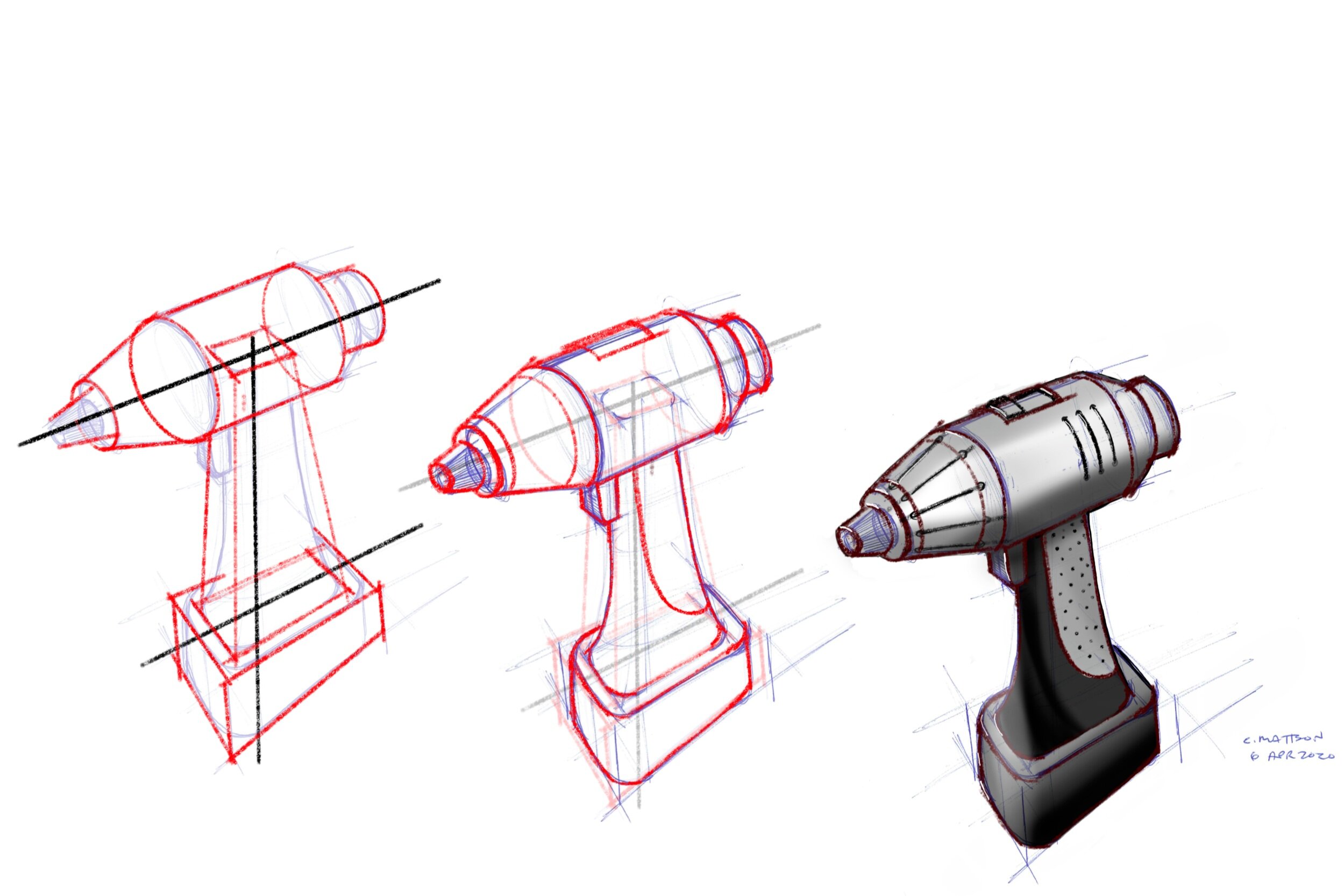
To be clear about the images in this article, I have manually sketched them using an iPad, Apple Pencil, and Autodesk’s free iPad app called Sketchbook. As shown directly below, shading and shadowing can be done by layering dark and light colors in software such as Sketchbook, or it can be done manually using just one pen/color and changing line density.

Whether created digitally or with paper and pen, the physics are the same.
Core Principle
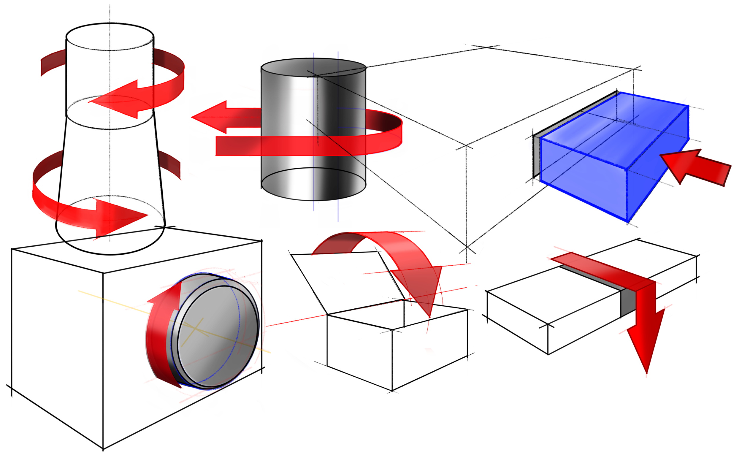
To shade and shadow an object, you must consider how light passes by and reflects off the object.
Step by Step Process
To produce the kinds of sketches you see above, follow this 8-step process.
Step 1: Sketch the object and choose a location for the light source. You will need to know the placement of the actual light source, and its projection onto the floor, as shown below.

Step 2: Identify the sides of the cast shadow. To do this (as shown below), draw a line from the light source (as projected onto the floor) past the near edge of the cylinder. Call the point where the line is tangent to the cylinder the near tangent. Draw a second line from the light location past the far edge of the cylinder. Call this the far tangent. To facilitate the next step, sketch a line in between the sides of the cast shadow as shown below.

Step 3: Find key points on the top of the cylinder. This will allow us to identify the far end of the cast shadow. To do this, first find the points on the top cylinder that corresponds to the near and far tangents. A line between those points bisects the cylinder end, as shown below. Make a second bisection that produces four equally sized quarters on the cylinder end.
As will be shown below, these lines are important because they indicate where the cylinder surface should be shaded dark and light. In the image below, these are labeled as the near normal line, near tangent line, far normal line, and far tangent line.

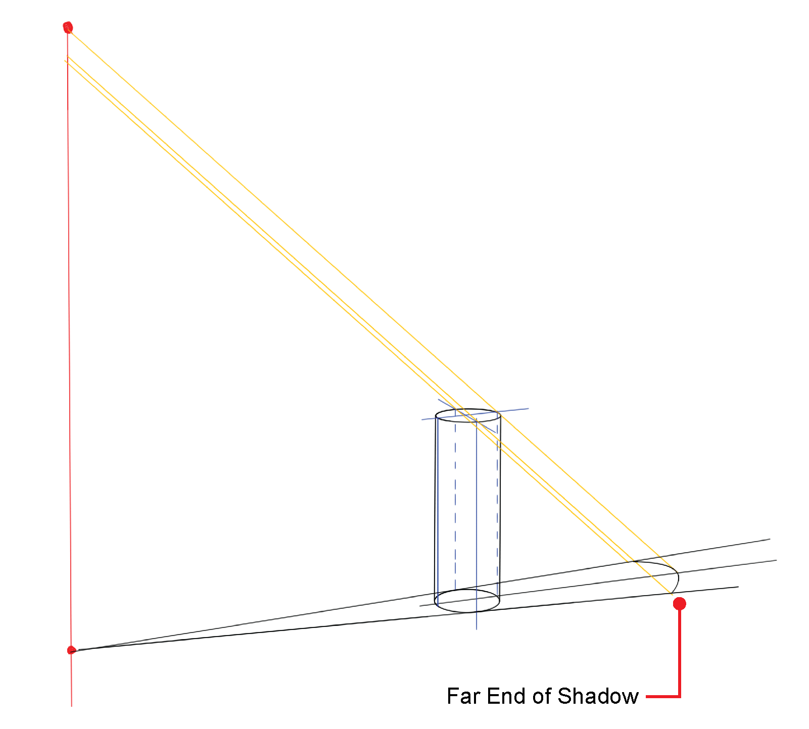
Step 4: Find the end of the shadow, as shown below. From the actual light source (at its height) draw a line past the far tangent point (on the top of the cylinder) to the far shadow line. Then draw a line parallel to the previous line, through the far normal point to the center line of the shadow. Then draw another parallel line through the near tangent to the near shadow line.

Step 5: Sketch the far end of the cast shadow. Do this by sketching an arc that connects the three points identified in the previous step, as shown below.
Step 6: Shade the cast shadow.

Typically shadows near an object are darker than the shadows far from the object. Note that the higher the light source, the more rounded the cast shadow will be at its end, and the lower the light, the more square the top of the shadow will be. This is simply because the cylinder looks like a circle from the top and a rectangle from the side.

Note that the closer the light is to the object, the more outward-flared the sides of the shadow will be.

Step 7: Shade the cylinder. First shade the area on the cylinder close to the near tangent line. To shade this well, it is helpful to consider the top view of the cylinder to better understand how the reflection is happening. This top view is shown below.

Notice how the light rays reflect differently off the object depending on where it hits the surface (see blue and green lines and where they hit they object). To make sense of the reflection, know that if we were standing at the light source, then most of the light that hits the cylinder normal to its surface (blue line), will reflect back to us and appear bright. On the other hand, the light that hits the cylinder tangentially (green line) would not reflect back to us, so it would appear dark.
Because we are not often standing at the light source, those reflections are shifted just a little, counter clock wise.
As shown below, there are generally three tones in the shading; a light tone where the reflection is greatest (shifted slightly from the near normal line), dark tone where the reflection is least (shifted slightly from the near tangent line), and mid tones in between, where light and dark are blended. Though there are only three tones, there are generally 6 shaded regions, as shown below.

Step 7: Shade the top of the cylinder. Again consider what is happening when the light reflects off this planar surface. It will have a generally uniform tone, which is darker if the light is low, and lighter if the light is high.
Step 8: Add tiny highlights and shadows. The edges of the cylinder, at the top, where the reflection is greatest will likely have a tiny highlight right at the edge. Likewise, there will always be a tiny gap where the object sits on the floor so, adding a slightly darker edge where it meets the floor produces a more realistic image.
Evaluation
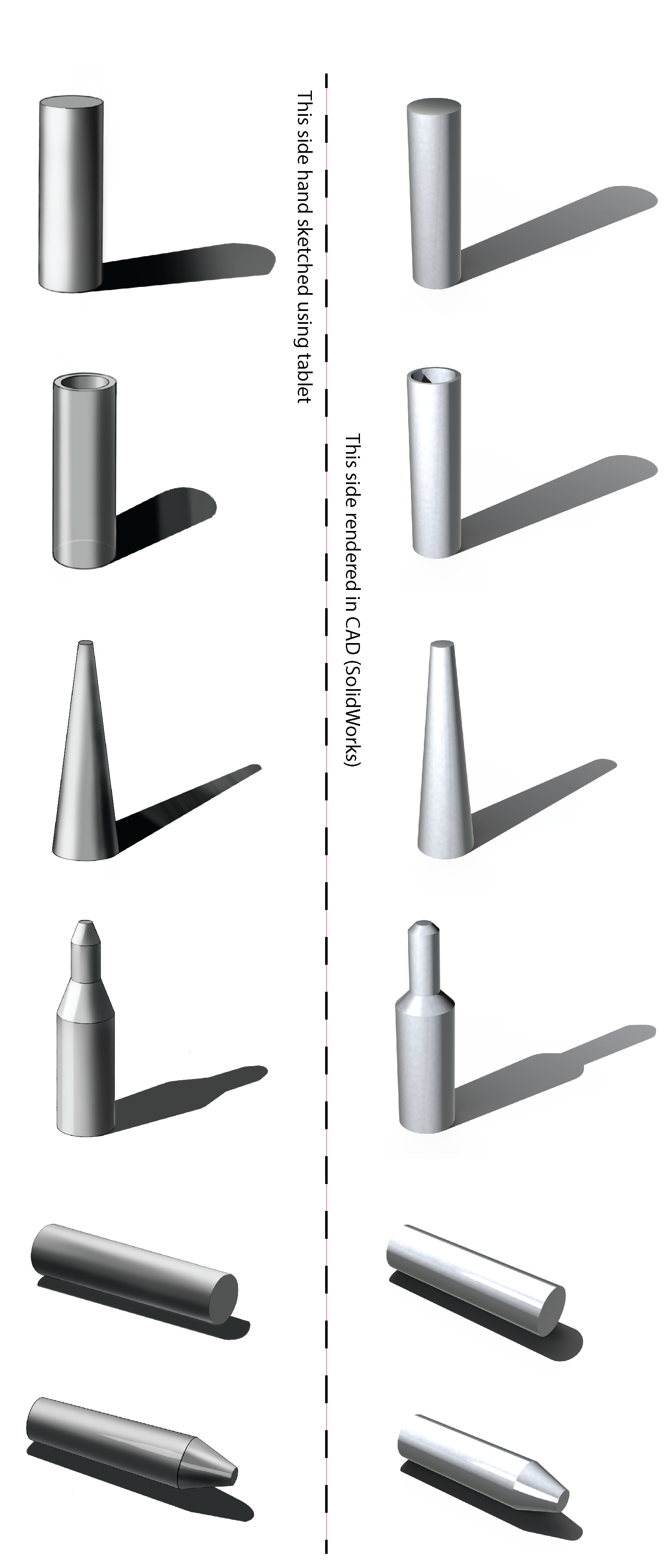
As a way of evaluating how well these steps produce expected results, consider the image below. On the left side are the cylinders I created manually using the step by step process above. On the right side of the image are similar shapes that I made and rendered in a solid CAD modeling software (SolidWorks).
Why this Matters
Clearly computer software such as solid CAD modeling can be used to produce great shadows and reflections for any part, so why is it valuable to hand shadow and shade objects? The reason is simple. Many critically important design decisions are made very early in the conceptual development of a product, way before CAD is involved. These decisions are often driven by simple sketches made on paper, post-its, white boards, etc. Couple this with the fact that often the idea that is selected for further development is not the best idea, but instead is the idea that is most clearly understood by the decision makers. Shading a cylinder gives it depth and shape that may have otherwise been lost if presented flat or as a side view rectangle.
Practice
From my own experience, I can say that creating a precise shadow/shading construction a few times for the shapes below will lock in the physics and allow you to quickly create approximate shading and shadowing that will ultimately make your ideas more understandable. To practice, download or screen shot the shapes below, then shade and shadow them. Further below, you’ll find my construction lines and a few notes that might help as you work through it. Good luck.

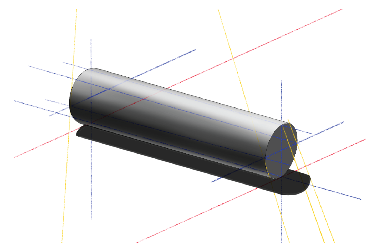
For the two cylinders laying on their side, put the light source mostly above and slightly behind the cylinder. This is a typical way of representing cylindrical objects on their side. After placing light source, bisect the end of the cylinder, vertically first. Then establish the floor (red line). Make parallel red lines at each end. Then bisect the cylinder horizontally.
Draw a light ray from the source past the near face of the far side of the cylinder. Where this yellow line crosses the red line determines where the cast shadow will be. To find the shadow edge, draw a line through that point, and parallel to the cylinder.
To find the other long edge of the shadow, first find the end of the shadow by passing light rays past the bisection points on the near face of the cylinder and making the shadow equally wide from the center to each long edge.
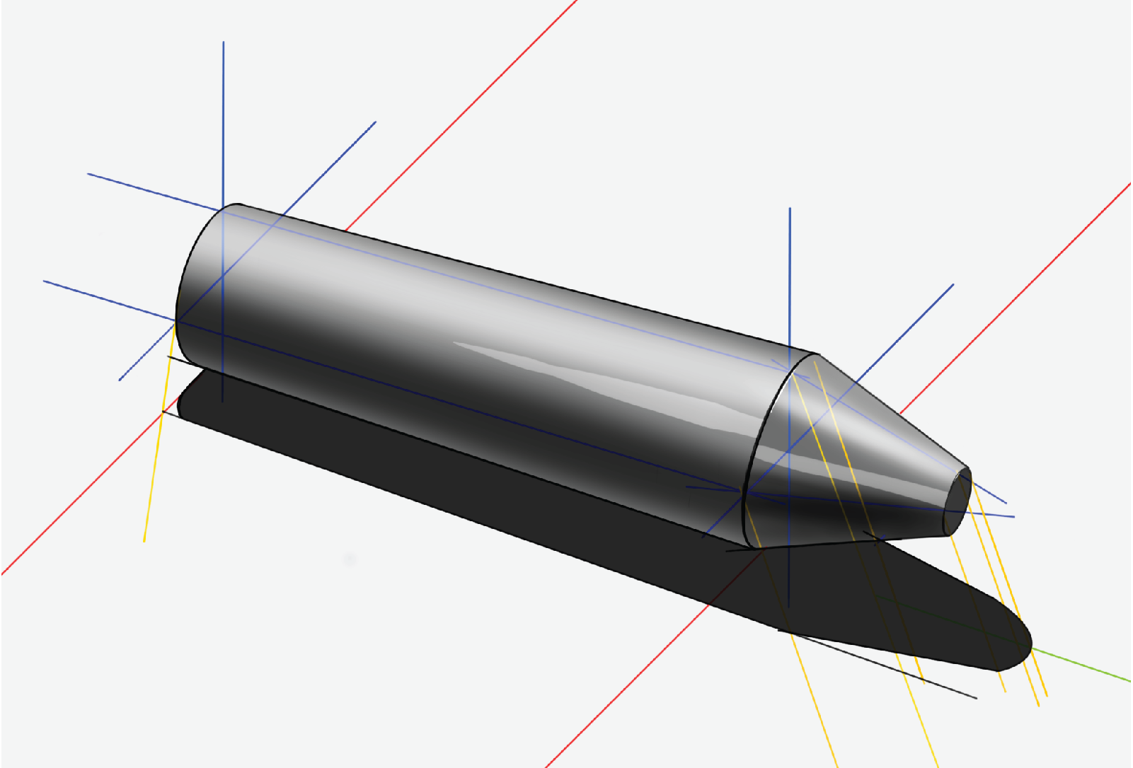
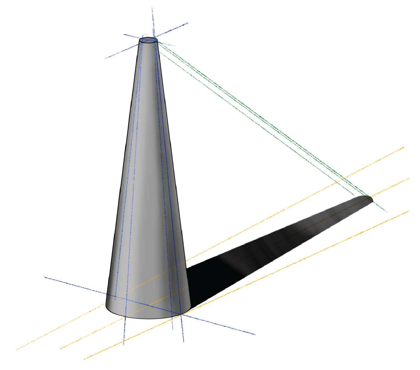
For objects like cones that decrease in size, sketch where the perfectly cylindrical cast shadow would be, then taper it inward as shown.
For objects with multiple size changes create many construction lines as shown. When shading the object, the highlights will generally be connected and be stronger on the angled faces since more light will reflect off it.

To cite this article:
Mattson, Chris. “Learn to Sketch: Shading and Shadowing Cylinders.” The BYU Design Review, 17 Jan. 2022, https://www.designreview.byu.edu/collections/learn-to-sketch-shading-and-shadowing-cylinders.