Engineering Design in Formula 1
The 2025 Formula 1 is quickly coming to a close, with the final race being held just days away (December 7th) in Abu Dhabi. For the first time in years, the drivers championship will come down to the wire, with three drivers (Max Verstappen, Lando Norris, and Oscar Piastri) all having a shot at the title depending on what happens in this last race. Clearly there is a lot of talent on the grid this year in terms of driving ability, yet many fans still wonder what engineering choices can give their team a competitive edge.
The sport of Formula 1 (F1) is both a racing competition and an engineering competition. The teams are tasked with the enormous challenge of creating the fastest car on the track. This involves a combination of both driving skill and engineering performance. Each team is required to follow a stringent set of design rules, dictated by the FIA that constrain the car's size, weight, and performance. It is within these strict set of design rules that engineers must adapt and innovate in order to produce the best performing car possible, giving their team the best chance at victory. This article explores the key features of an F1 car, and the design choices that must be made to optimize its performance. These design choices are driven by several fundamental mechanical engineering principles, including tire grip and aerodynamics.
Aerodynamics in Formula 1
Simply stated, aerodynamics is the study of how moving solid bodies interact with air particles. Seeing that F1 cars are solid bodies moving through the air at high speeds, it immediately becomes clear why the study of aerodynamics plays such a large role in the research and development of these cars. Two key features of aerodynamic components in any race car are airfoils and ground effect. Airfoils follow the general shape of a wing, creating a pressure differential that generates lift. Unlike a wing on an airplane, the airfoils on F1 cars are designed to create a negative lift, which pushes the cars into the ground to improve traction. This can be especially useful when cornering at high speeds. Airfoils are most prominently used for the car’s front and rear wings. Teams have the creative liberty to test and develop innovative airfoil designs and configurations that allow for faster lap times. A small change in the aerodynamic shaping of the car may lead to fractions of a second difference for a lap time, which can amount to a significant advantage over the entire race [1].
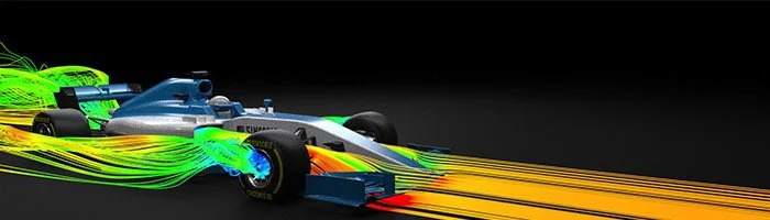
Figure 1: A model simulating airflow over the body of a formula 1 car. The streamlines show how air is pushed through the airfoils. [2]
Another key component of the aerodynamics design on an F1 car is the ground effect. Ground effect is a term used to describe the shaping of the car's undertray, which is optimized to create low pressure underneath, sucking the car down for massive grip with little drag [3].
The undertray of a Formula 1 car is highly regulated by the FIA and must meet certain criteria such as height and flatness. The undertray contains a diffuser, which channels air out the back of the car, generating lower air pressures and greater traction. The undertray has a large surface area that is exposed to much of the fast moving, low pressure air, and as a result it produces 40% of the overall downforce on the car.
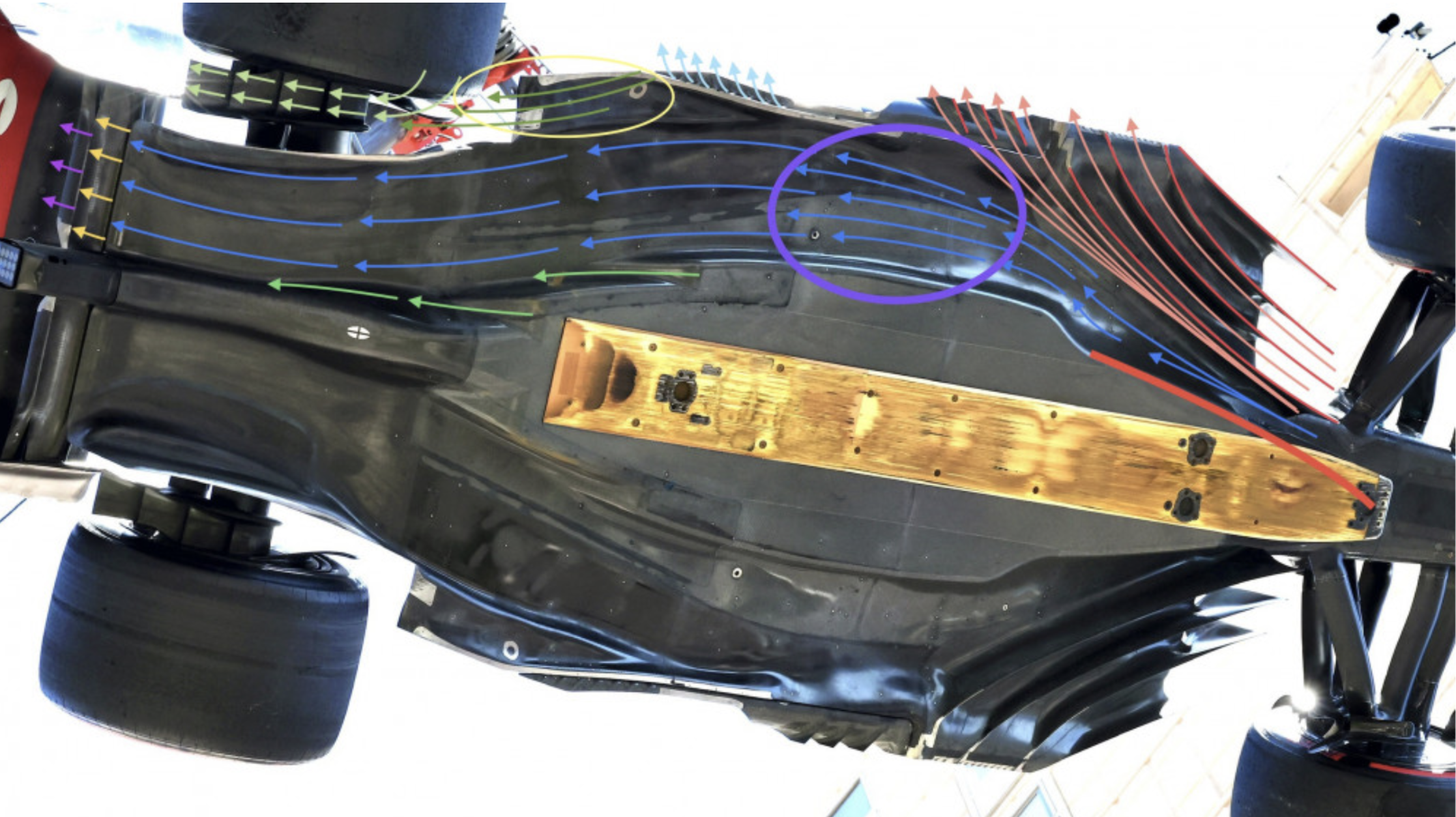
Figure 2: This image depicts the unique underlay of a Formula 1 car. The arrows demonstrate how air will move through the diffuser and out the back, creating a very fast and controlled airflow [4].
Testing in Formula 1
An important aspect of aerodynamic design in testing. It is very expensive and impractical to measure the effect of every design change on the car in real racing scenarios. Teams rely heavily on testing to develop their designs because of this. The most common methods are wind tunnels and Computational Fluid Dynamics analysis.
In a wind tunnel, the car is placed on a moving belt, so that the wheels can spin at normal speeds and fully simulate the real world effects. Each wheel is mounted in place, to prevent the car from moving, and sensors are placed under each wheel to detect drag forces. Sometimes a scaled down model of the car is used, or even a scaled down single component [5].
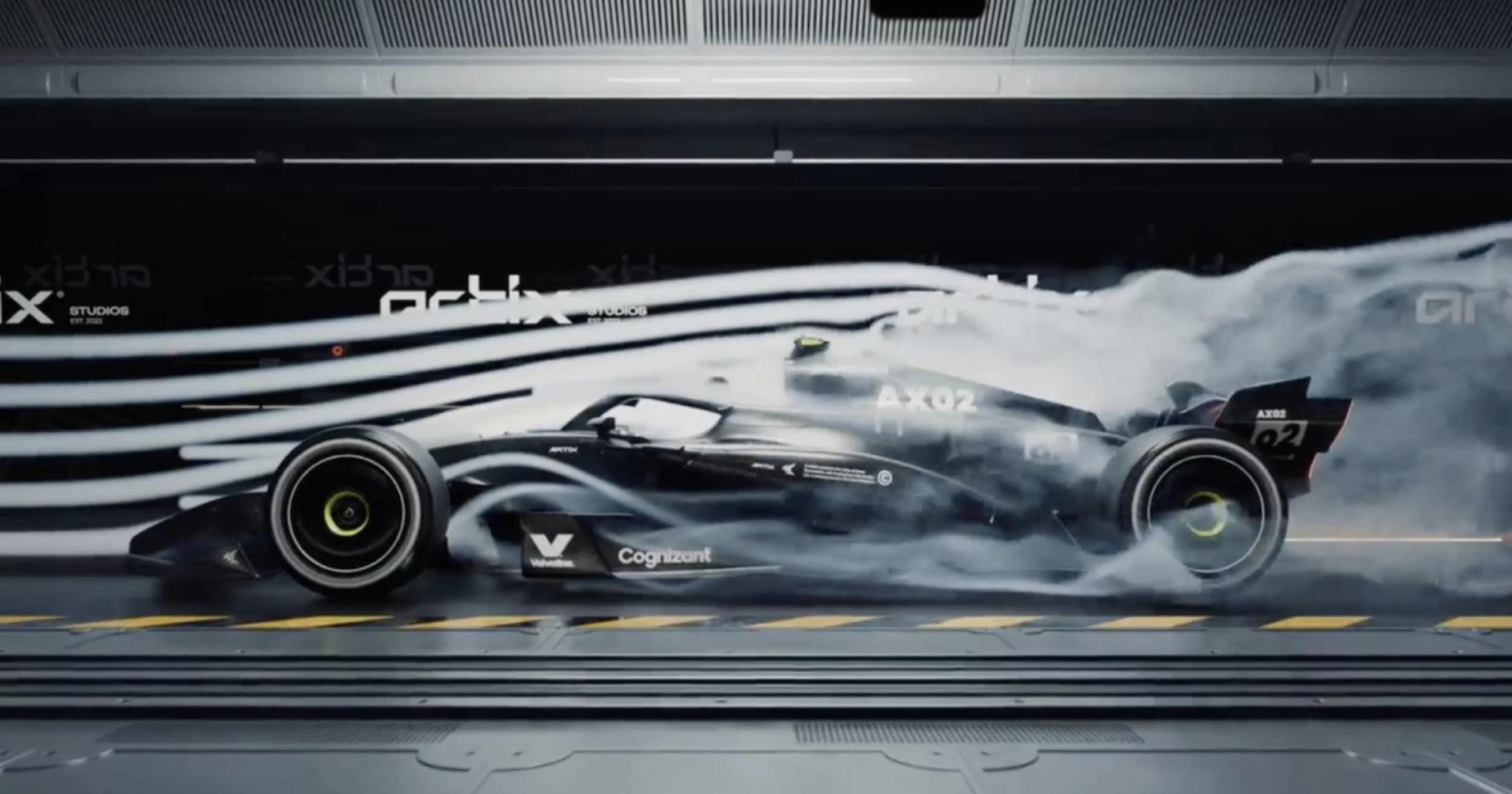
Figure 3: Formula 1 car in a wind tunnel [4].
Wind tunnels are expensive and must provide very precise airflow in exact conditions in order to effectively model the real world aerodynamics. Because of this, engineering teams often use Computational Fluid Dynamics (CFD) software to simulate airflow. CFD programs are simulations that solve a differential analysis of airflow around the car. Teams use it to test wing shapes, floors, and airflow channels without building the actual parts. It shows where pressure is high or low, where vortices form, and where drag originates [6].
Tires in Formula 1
Tires are another design choice that team engineers must make to optimize track times. Tires are the only part of the car that actually makes contact with the ground, and they can greatly impact the performance. In Formula 1, each tire is manufactured by Pirelli. There are several different options ranging from slick, smooth tires to treaded tires for rainy conditions. Slick tires provide the most grip, but they also wear out the quickest, requiring more pit stops [7]. Engineers must consider track conditions, temperature, and overall race strategy to decide what tires to use and when to use them.
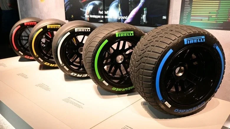
Figure 4: This image shows the various tire types provided to Formula 1 teams [8].
It is clear that engineering influences every aspect of the sport of Formula 1. While we may not know how the championship will play out at the end of the season, we do know that behind each successful diver is a team of dozens of engineers who work tirelessly to ensure that each car performs well enough to compete for the podium.
References
[1] “Downforce and why F1 cars have wings” Formula 1, https://www.formula1.com/en/latest/article/f1-explains-downforce-and-why-f1-cars-have-wings-with-mclaren-aero.10xj8CJPz8s7CmwfoyWmCU
[2] “Computational Fluid Dynamics in Motorsports” Racecar Engineering, https://www.racecar-engineering.com/advertisement/fluid-dynamics-in-motorsport/
[3] “Race Car Aerodynamics” Gregor Seljak, http://www-f1.ijs.si/~rudi/sola/RaceCarAerodynamics.pdf
[4] “F1 Car Wind Tunnel Simulation” EmberGen, https://80.lv/articles/f1-car-wind-tunnel-simulation-with-embergen-blender
[5] “Feature: Downforce in Formula One, Explained” AMG Petronas, https://www.mercedesamgf1.com/news/feature-downforce-in-formula-one-explained
[6] “CFD in F1” Raceteq, https://www.raceteq.com/articles/2024/10/cfd-performance-in-f1
[7] “The beginner’s guide to F1 tyres” FIA, https://www.formula1.com/en/latest/article/the-beginners-guide-to-formula-1-tyres.61SvF0Kfg29UR2SPhakDqd
[8] “The Tire Compound Ranges Used In F1” Jalopnik, https://www.jalopnik.com/1905757/soft-medium-hard-tires-formula-1/
[9] “Aerodynamic Floors and Diffusers in F1” Fluid Jobs, https://fluidjobs.com/blog/aerodynamic-floors-and-diffusers-in-f1-how-do-they-work
To cite this article:
Engle, Josh. “Engineering Design in Formula 1.” The BYU Design Review, 1 December 2025, https://www.designreview.byu.edu/collections/engineering-design-in-formula-1.