Engineering Design in Artemis II
NASA once again captured the world’s attention on April 1st, 2026, launching the second Artemis mission (known as Artemis II) around the Moon, this time with astronauts on board. While the four intrepid astronauts (Reid Wiseman, Victor Glover, Christina Koch, and Jeremy Hansen) hurled toward the Moon, the gaze of millions around the world turned to the heavens, wondering what scientific advancements a mission like this could bring, and what effect it might have on the trajectory of human civilization. The purpose of this mission was to further prepare for building a permanent research base on the Moon, which would be the first in human history.
As planned, the Artemis mission concluded ten days later, with the Orion space capsule splashing down in the Pacific Ocean on April 10th, 2026, just off the coast of San Diego. This mission proved to the world that humans can return to the Moon and also set several records of its own. The astronauts traveled farther from Earth than any previous crewed mission, breaking the Apollo 13 record set in 1970. Additionally, the Artemis II mission included the first woman (Christina Koch), the first Canadian (Jeremy Hansen), and the first person of color (Victor Glover) to travel beyond low-Earth orbit.
As of the time of this article’s publication, it has been a couple of weeks since the completion of Artemis II. Now that all official publications and photographs have been released, it is a good time to reflect on some of the most notable engineering design decisions made by NASA in the Artemis II mission.
The Orion Spacecraft
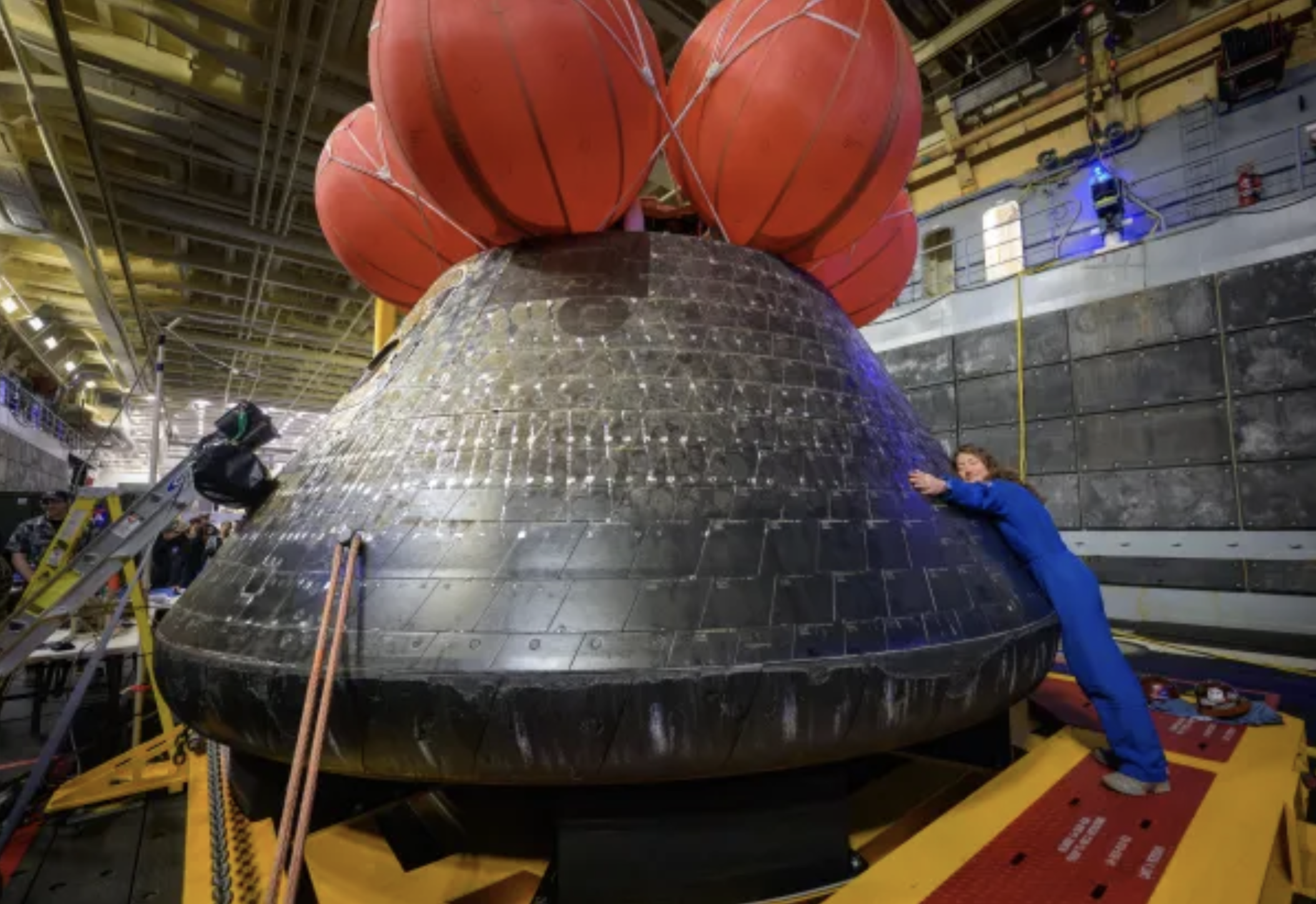
Figure 1: The Orion Spacecraft, the small gumdrop shaped capsule that returned to earth [1].
Anyone who watched the return to Earth and splashdown on April 10th would instantly recognize the Orion capsule shown above. This small vehicle is what brings the four astronauts back to Earth. Engineers designing the capsule have no easy task. It begins to enter the atmosphere at speeds of around 25,000 mph, a blistering Mach 32.6! Within just 13 minutes, the capsule must slow from 25,000 mph to a splashdown speed of roughly 20 mph as it lands in the ocean. Orion moves so fast through the atmosphere that it compresses the air in front of it faster than the air molecules can move out of the way. This is known as adiabatic compression, or shock heating. The resulting shock waves surrounding the capsule create a thin layer of extremely hot plasma, reaching temperatures of up to 5,000°F around the vehicle’s exterior.
Although it may seem to contradict intuition about aerodynamics, engineers intentionally designed the Orion capsule with a large, blunt base for a very specific reason. The wide, flat surface generates a strong shock wave that forces the hottest gases to flow around the capsule instead of directly against it, creating a protective buffer that keeps extreme heat away from the spacecraft’s surface. In addition, engineers use a heat-resistant material called Avcoat around the capsule. This material gradually ablates during reentry, meaning it burns away in a controlled way to absorb and carry off heat, further protecting the crew inside.
Launch Abort System
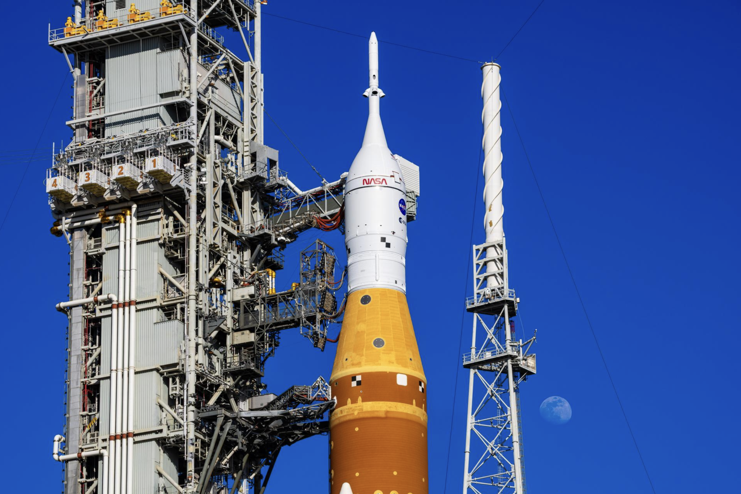
Figure 2: The Launch Abort System, the pointy white tower atop the rocket [1].
One of the main goals of Artemis II was to demonstrate that deep space travel can be safe and dependable. As part of this effort, engineers developed an innovative safety system known as the Launch Abort System (LAS) for the overall Artemis Space Launch System (SLS).
Engineers from Lockheed Martin and Northrop Grumman were brought in to develop the mechanical structure of the LAS. As seen in Figure 2 above, the LAS is a 44-foot white, pointed tower that sits atop the Orion spacecraft, where the astronauts are located. Of course, the most valuable cargo of any rocket is its crew, so engineers placed special emphasis on ensuring they could rapidly separate the astronauts from the rocket in the event of a launch emergency, such as an engine failure. In operation, the LAS fires abort motors, the three smaller rockets visible on the tower, to pull the Orion capsule away from the launch vehicle. Once it reaches a safe altitude, a jettison motor separates the tower from the capsule, allowing Orion to deploy its parachutes and safely return to Earth.
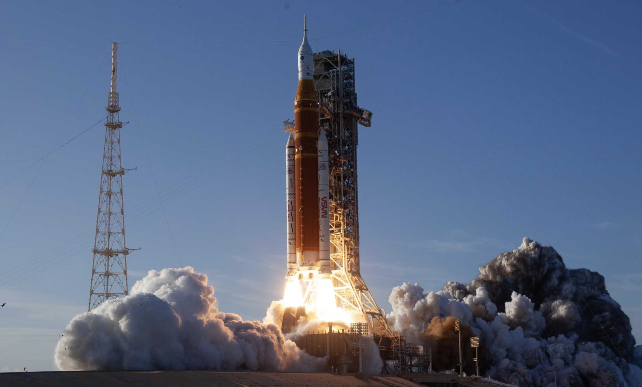
SLS Propulsion
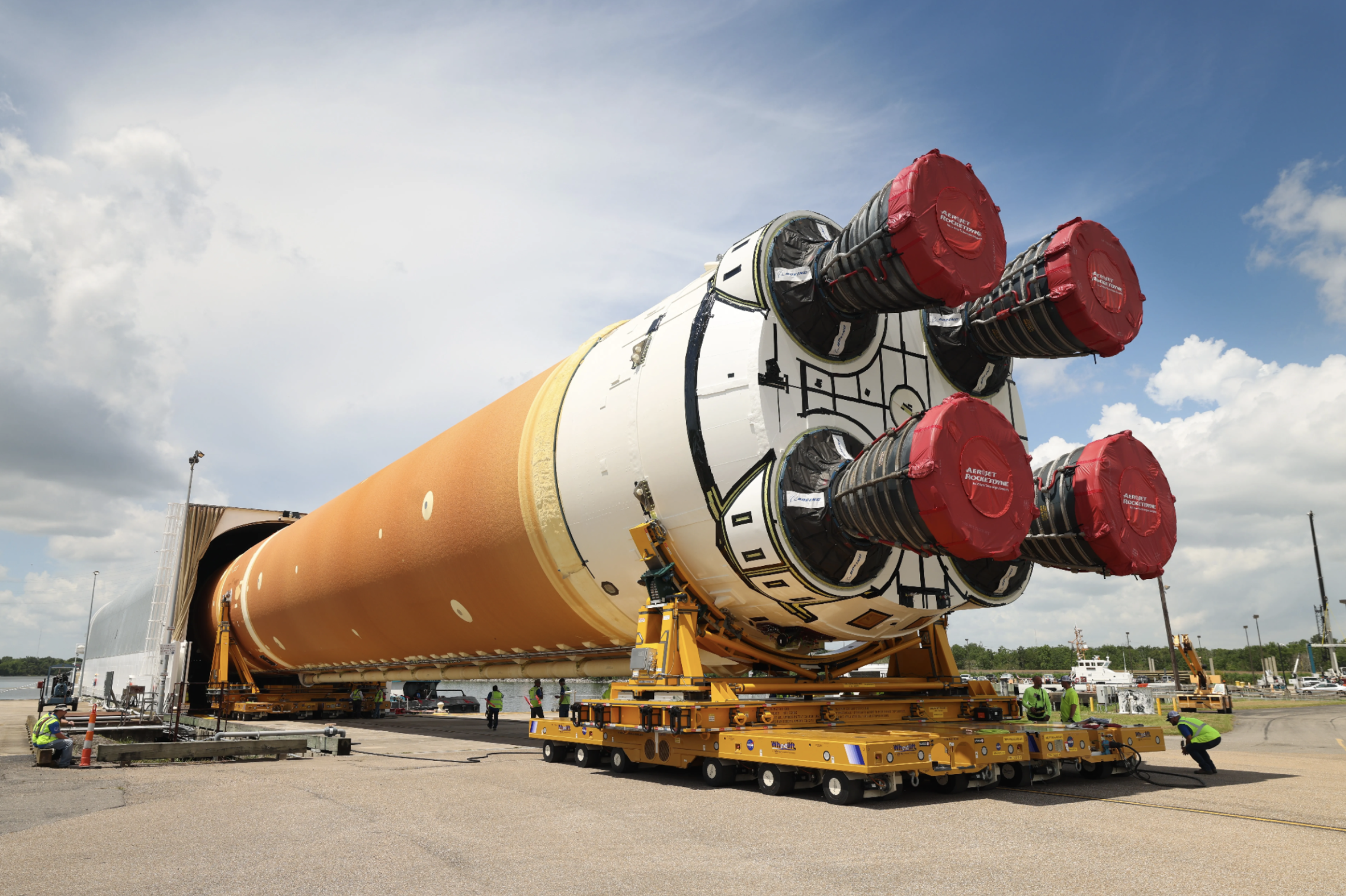
Figure 3: Space Launch System Core Stage for Artemis II Rocket Loaded onto Pegasus Barge [1].
One of the most impressive features of the Artemis II SLS is its propulsion system, namely the two solid rocket boosters on either side and the SLS core stage in the center. Combined, these systems produce a massive 8.8 million pounds of thrust, more than even the Saturn V rocket used during the Apollo missions. The majority of this thrust comes from the two solid rocket boosters, built by Northrop Grumman. These 177-foot boosters each generate around 3.6 million pounds of thrust for about two minutes, after which they separate and fall back into the ocean.
The SLS core stage (seen above) consists of four RS-25 engines. These are “heritage” engines that previously flew on the Space Shuttle but have been modernized with new controllers and improved insulation. Together, they burn roughly 90,000 gallons of liquid hydrogen and liquid oxygen every minute, producing a combined 2 million pounds of thrust for about eight minutes before separating from the upper stage. During this phase, the core stage must burn long enough to accelerate the vehicle to over 17,000 mph, placing the Orion spacecraft and its upper stage into a stable, highly elliptical Earth orbit.
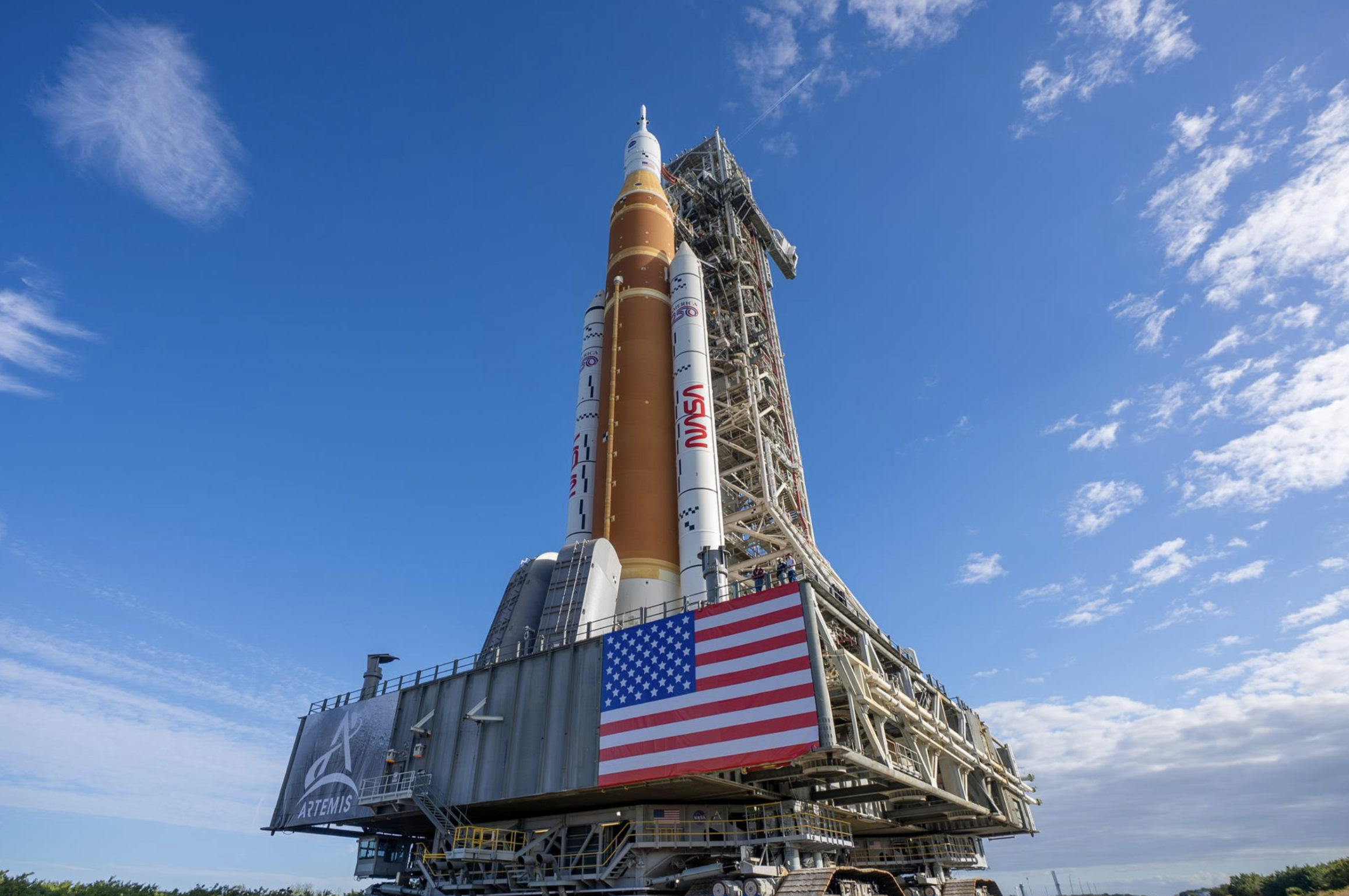
Figure 4: NASA’s Artemis II SLS Rocket and Orion Spacecraft Rollout to Launch Pad 39B [1].

Figure 5: A setting Earth [1].
There are so many amazing engineering design lessons to be learned from Artemis II. Included below is a link to NASA’s official site, where all of these images were sourced from. It is worth taking a look at other images in the Artemis II gallery and continuing to learn more about the amazing engineering that went into making this mission possible.
References
[1] "Artemis II Multimedia." NASA, National Aeronautics and Space Administration, 2026, www.nasa.gov/artemis-ii-multimedia/#images. Accessed 29 Apr. 2026.
To cite this article:
Engle, Josh. “Engineering Design in Artemis II.” The BYU Design Review, 29 April 2026, https://www.designreview.byu.edu/collections/engineering-design-in-artemis-ii.