What is Systems Design? Part 3: The Case for Model Based Systems Engineering
Systems Design is performed at many levels of integration in large and complex systems such as satellites, aircraft, and transportation systems. How are all these intermediate designs coordinated to fit and work together? We call it “Systems Engineering and Integration.” Let’s start by summarizing this series of articles so far.
“What is Systems Design?” [1]. In Part I, John Salmon enumerated the broad use of the word “System,” arguing it is “used, reused, and even abused in numerous ways…” citing examples that cause confusion and limitations. He then concurs that the word works well in many cases and “we’ll have to live with this limitation” for a time. In Part 2 our eyes are open to the spectrum of “system design” which ranges in size and scope from smaller elements, materials and parts to ever increasing levels or sizes of assembly in words like components, subsystem, system, and system-of-systems [2]. A sample system decomposition is shown in Figure 1.
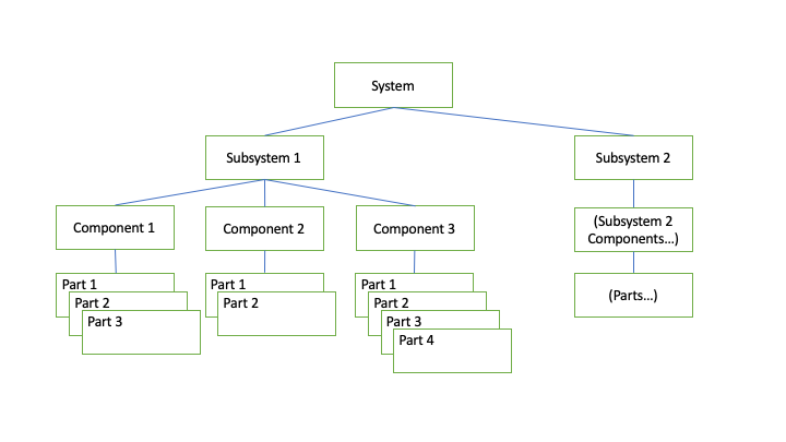
Figure 1 - Sample System Decomposition
Here in Part 3 we tackle the challenge of performing systems design at various points on the system design spectrum in a planned and coordinated manner such that all designs, small and large, are properly specified, decomposed, allocated, tested, and integrated into a desirable and successful complete system. To do so, we’ll use the industry term, Systems ‘Engineering.’ Systems Engineering is the set of activities resulting in concepts of operations (ConOps), market or customer requirements, functional and logical system decomposition, interface management, and verification (e.g. test, analysis, simulation). Systems Engineering artifacts (e.g. specifications, decomposition and interface diagrams, test plans and procedures) are traditionally captured in disjointed text-based documents, spreadsheets, and diagrams. This traditional process often results in errors and unnecessary costs due to ‘cut-and-paste’ of data from one tool to another (e.g. from Excel to Powerpoint, or from Visio to Word. Costs also rise when needed system changes require all artifacts to be changed in various tools and throughout all levels of decomposition. As will be shown next, Model Based Systems Engineering, or MBSE performs the same tasks but utilizes fewer tools and a planned digital, “integrated, coherent, and consistent system model,” [3] to reduce the errors and cost of maintaining all artifacts.
Let’s illustrate. Please join us in a ‘change control board’ (CCB), a meeting to take action on a proposed system design change, at a company we’ll call Bighorn Systems.
“Welcome all to this week's CCB.” Greg Adams, the chief engineer on the BlueJay project looks disappointingly around the conference table with half the chairs empty. “Where is everyone?”
“Fred from Manufacturing had a conflict,” said Bill the program manager, “and Lucy… well she said something came up.”
Greg sighed. “Well, we’ve got to push forward anyway, so…” Greg gestured to the monitor and continued. “Due to the less than desirable performance of our prototype last week, our customer has decided to change the required performance range from 2000 to 3000 miles per refueling, to give more margin. This will result in an impact to…”
“But Greg,” Bill interrupted. “If you change the range requirement, we’ll have to flow that requirement down to our tank supplier and…” Bill took a deep breath, “it will impact the overall design, test plan, prototype design, analysis spreadsheets… not to mention the requirements documentation. The cost will be…”
“Not only that,” Betty, the project coordinator, jumped in. “but we’ll have to go through each document and find every occurrence of the range requirement and change it. On the last project we never did find all the needed changes. It was a disaster.”
Greg slouched in his chair with sweat down his face, speechless.
“Don’t forget,” Bill added, “We’ll have to change the revision identifier again on all these documents to keep track of all the changes. Unless…” Bill scratched his head. “Unless we just make the design changes without changing the revision letters?”
“Are you kidding?” Greg leaned forward. “That probably made our customer concerned in the first place. If we don’t keep our documents consistent from top to bottom, we’ll never know exactly what we have and what we really built. We’ll be lucky to have it all fit together. Besides, they are only raising the range requirement to manage risk. We caused their low confidence by our poor control of our prototype.”
Bill threw up his arms. “Why can’t we have a single source for all this information? Why does it have to be scattered over all these tools, word processors, file-shares, analysis tools, and artifacts?...”
This scenario happens over and over in many companies and projects. Sure, we should make every attempt to minimize ‘design changes;’ but new requirements often come, the design will evolve and for a number of reasons, designs need to be adjusted. Wouldn’t it be nice to make the change, as Bill pleaded, in one place such that the change will automatically propagate throughout all artifacts and assembly levels? Enter Model-Based Systems Engineering (MBSE) where we plan and associate model elements with, where possible a single source, or at least an authorized minimal set of sources of truth for each piece of design information.
In MBSE, we still perform the design activities at each and all levels of assembly and create similar transferable artifacts so that the product can be produced; but in MBSE each element of information, each design decision and choice is captured once in a system model then referenced in every usage at other levels of decomposition and assembly. Each artifact usage (such as in various views) are secondary to usage in the primary system model. For example, a model element representing a subsystem (e.g. an aircraft jet engine) is represented once in the model, and twice in a system decomposition diagram, assuming there are two identical engines on the aircraft. The diagram includes two blocks related to the one engine defined in the model. A change of the primary source-of-truth, the engine in this example, automatically results in changes to the secondary usages [3].
There are a number of software tools or applications (see General Resources below) on the market to facilitate this orchestration of system data. One of the primary languages used by these tools is SysML (systems modeling language), “a general-purpose graphical modeling language for specifying, analyzing, designing, and verifying complex systems” [4]. SysML evolved in recent decades. The Object Management Group (OMG) carried the baton and various languages including UML (Unified Modeling Language) were developed to support specific industries. UML is, “a general-purpose modeling language that is intended to provide a standard way to visualize the design of a system”[5]. SysML, based on UML, was created to support and integrate large-systems engineering [3].

Figure 2 - Relationship between MBSE digital System Model and Design Artifacts
Here’s how it works (reference Figure 2 and the architecture for a simple aircraft with two engines). In practice the system architects (the top level systems engineers) develop the system level model of the aircraft and associated artifacts (e.g. requirements, key performance measures, verification or test planning, etc.) then decompose (identify and allocate) to the next level subsystems such as aircraft avionics, propulsion (engines), structure (fuselage and wings), environmental controls, landing gear, etc. Then the subsystem teams develop the subsystem level model and associated artifacts and requirements for suppliers to develop the component and part level models and artifacts. Lower level design teams follow a similar process for their respective components as needed. Required changes are managed through a coordinated CCB, then implemented in the system model and propagated throughout the artifacts.
As parts are acquired and components are produced, verification results are captured and added to the respective model for traceability to assure all requirements are met. Likewise as components are assembled into higher subsystems, and subsystems assembled into the system-of-systems, verification results at each level are captured in the model for traceability and total system verification prior to delivery to the customer or market.
MBSE tools and language provide far more benefits than just change management. SysML provides tools for structure (logical, interface, and physical architecture) and behavior (state machines, input/output, and simulations) development of the system and its components. In Part 4 we will show a SysML example with primary model, secondary artifacts and behavior development for a simple system.
References
[1] Salmon, John, What is Systems Design? Part 1, BYU Design Review, 2023
[2] Salmon, John, What is Systems Design? Part 2, BYU Design Review, 2023
[3] Delligatti, Lenny, SysML Distilled - A Brief Guide to The Systems Modeling Language, Addison-Wesley, 2014
[4] Object Management Group, https://www.omgsysml.org/what-is-sysml.htm
[5] Wikipedia UML, https://en.wikipedia.org/wiki/Unified_Modeling_Language
General Resources:
NoMagic Documentation (see Model Browser): https://docs.nomagic.com/display/MD190/Model+Browser
SysML.org: (See link: sysmltools.com): https://sysml.org
To cite this article:
Hardman, Ken. “What is Systems Design? Part 3: The Case for Model Based Systems Engineering.” The BYU Design Review, 26 Apr. 2023, https://www.designreview.byu.edu/collections/what-is-systems-design-part-3-the-case-for-model-based-systems-engineering.