Beyond Paper: How to Make Origami Out of Thick Materials
Introduction
Do you wish you could take your origami crease pattern beyond paper to a 3D model? Would you like to include origami design as one of the tools in your design toolbox? Do you want to use origami principles in design, but just don’t know how? If you’ve ever considered these questions, you’ve come to the right place.
Many people either know about origami, have seen others fold origami, or have folded it themselves, but very few people can translate origami crease patterns into 3D objects and designs. That skill is necessary to take origami from a hobby to an engineering tool. I want to push your origami knowledge and exposure just a little deeper and go beyond the paper pattern. Specifically, after reading this article, you’ll be able to make an origami tessellation pattern out of materials thicker than paper.
Learning this process can teach you origami design principles, which will help you in other designs. Because of origami’s unique characteristics, it can be a disruptive design in many fields; it has been proposed as consumer products (backpacks, toys), tools in the medical industry (stents, minimally invasive surgical grippers), and in space exploration (as deployable antennas and heat shields), and there are many other fields that have untapped origami potential. Those who can design with origami place themselves into a small group that sets them apart from others; if that doesn’t pique your interest, consider using this as a gift, a fidget toy, or desk ornament.
I’ll give you an as-generalized-as-possible guide on how to make thick origami in engineering materials, and while this how-to article will highlight one technique, the principles can apply to many other origami design scenarios. Keep reading, and you will learn a technique to make origami designs with non-zero thickness, extend your design toolbox, and make something cool!
Preparation
Unlike folding an origami crease pattern which may only take several minutes, designing a thick 3D origami model and assembling may take several hours. This tutorial assumes you have access and experience with CAD modeling software, 3D slicing software, a 3D printer, and tape.
Tutorial and Design Process
This tutorial will undoubtedly sacrifice some detail and some generality in favor of keeping things simple (academic papers on origami design can be very dense, making it difficult for those just starting). However, the process we use is the same that deployable origami designers around the world use: (1) choose a pattern, (2) account for thickness, (3) select hinges, and (4) assemble. Without further ado, let’s jump in!
Selecting a Pattern
There are endless YouTube folding tutorials for thousands of origami crease patterns for origami, and more are developed every day. With all these patterns, choosing one can be very difficult. You might not know which pattern to choose, and not every pattern is amenable to every application. To avoid high complexity at the beginning of your origami journey, we’ll adopt several constraints, and we'll focus on a space application. We should pick a tessellation, and, for now, let’s avoid patterns with a high number of unique vertices. Shown below are several popular patterns, commonly used in space applications.

Figure 1. Common deployable origami crease patterns proposed for use in space. Originally published in [1].
We will select the Tachi-Miura crease pattern [2] for its simplicity. It is composed of degree 4 vertices only (when 4 crease lines meet at a single point), which is one of the fundamental origami folds. For beginners, I would recommend the Tachi-Miura, the Waterbomb, or Diamond (Yoshimura) crease patterns. With a pattern selected, let’s create a 2D model of the crease pattern in CAD (as a sketch), which we will use to create the 3D models of the panels. Since the crease pattern is composed of repeating units, we need only sketch one repeating unit, and then we can put many of the units together in the assembly. I omit the small triangle shapes on either side for simplicity.
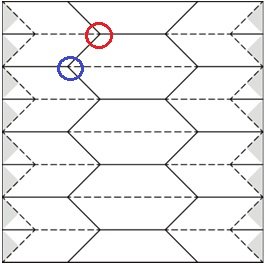
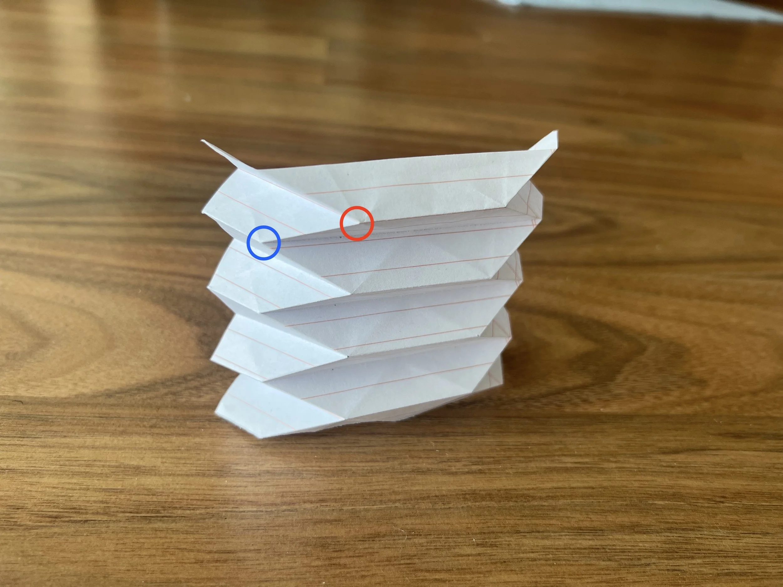
Figure 2. Tachi-Miura crease pattern from [2], modified slightly. The solid lines are mountain folds, the dashed are valley folds. The triangle panels on the sides are left out for simplicity. The two unique vertices are circled. All other vertices are either repeated or are reflections of these two vertices. The image on the right shows the crease pattern folded in paper, partially deployed.

Figure 3. One repeating unit of the Tachi-Miura Crease pattern, sketched in CAD, showing the dimensions (in mm) used for this tutorial. These lines are a part of a single sketch that is then referenced several times to make separate components. The panels are numbered for future reference.
One word of caution. I suggest limiting the repeating units to about four or less for your first time. More than this and you may get overwhelmed. It is also beneficial to select a pattern with symmetry; this will cut the burden of thickness accommodation in half.
Thickness Accommodation
As engineers, we are constantly making assumptions. In origami paper folding, we make one very crucial assumption: that the material has zero thickness. This assumption works well for paper prototypes, but is no longer valid when using thick engineering materials. Just as in any design scenario, the design needs to change as the assumptions change. So, we must make some adjustments to fold the pattern as desired; this will be the most difficult step of our process.
In the origami design field, we call these adjustments applying a thickness accommodation, and while there are many thickness accommodation techniques to choose from, some are easier to apply than others. We’ll start off with a moderately complex method that is commonly known as the Offset Panel technique [3].
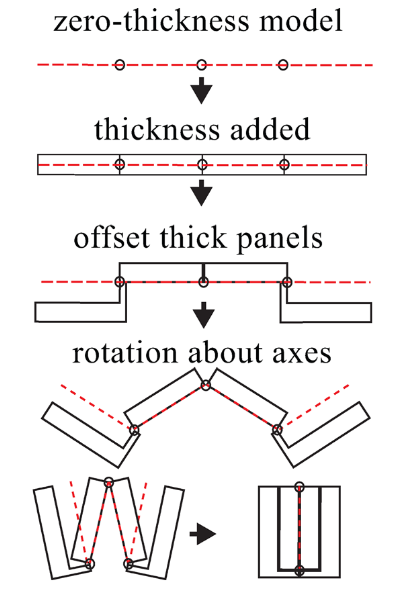
Figure 4. The Offset Panel thickness accommodation technique, as published in [3]. The image progresses from top to bottom in 5 different stages and is as if you were looking at a piece of paper from the side and all you could see was the thickness of the paper. The red dashed line represents the paper model.
As stated in [3], “This [thickness accommodation] technique is implemented via a series of steps: thickening the origami pattern’s panels, stacking the panels in the fully folded position, selecting a zero-thickness reference plane, creating offsets that join the stacked panels to the rotational axis locations of the zero-thickness origami model, and modifying panels to avoid self-intersection.”
For this pattern and thickness accommodation combination, we’ll start by giving each panel a thickness of 5 mm (2.5 mm in both directions). We then assemble these and place the assembly constraints at the zero-thickness creases as defined by the crease pattern.

Figure 5. Panels 1-4 with thickness added and constrained, in the open position. The light blue lines represent the zero-thickness crease pattern (these are the creases that are constrained to be coincident to each other). The unique red and blue vertices are circled.
This assembly works great until you try to fold the panels: there is interference. Since folding is the whole point of origami, we must remove/add material to permit folding.
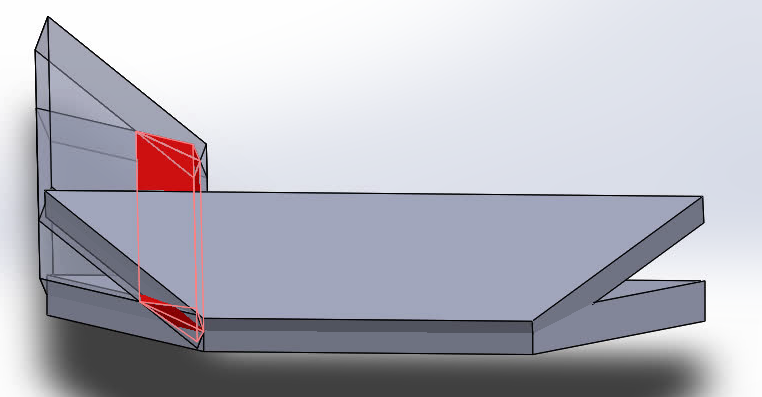
Figure 6. Interference between Panels 1 and 3, shown using interference detection.
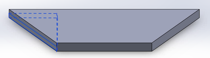
Figure 7. Panel 3. The blue-outlined material is removed to give space for Panel 1 when closed. The same is done to the right side of the panel.
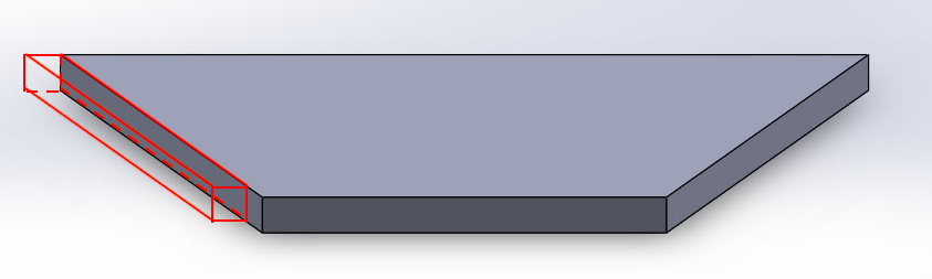
Figure 8. A second screenshot of Panel 3. The red outlined material is added to give a crease line for Panel 1 to attach to. The same is done to the right side of the panel.
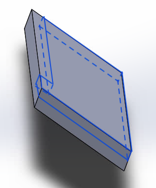
Figure 9. Similarly, material is removed from Panel 1 to allow nesting in the closed position.
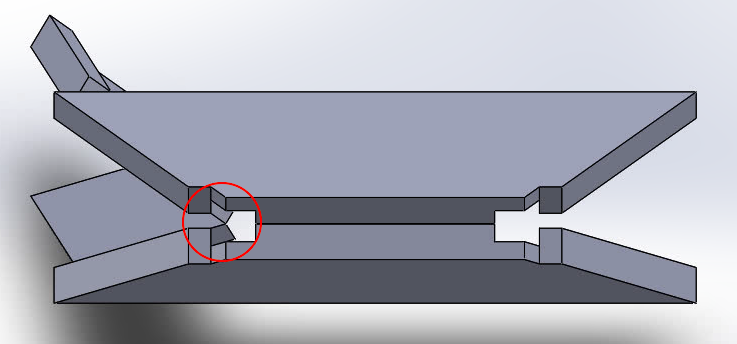
Figure 10. The finalized red vertex, after thickness accommodation applied.

Figure 11. The finalized vertex, after thickness accommodation applied, viewed from the back side.
Thankfully, because of the symmetry of this pattern, most of the work is done. Now, Panels 2 and 4 are created by reflecting parts of Panels 1 and 3 respectively. They are then assembled together. You may have noticed that I didn’t assemble these at the zero-thickness line (which is what you would normally do). Instead, I moved the hinge line using a technique called the Hinge-Shift thickness accommodation technique, which is a simple technique that helped avoid additional panel modifications. The Hinge-Shift can be used in many situations and in combination with many other techniques; more details on this technique can be found in [3].
Select Hinges
For many origami applications, the hinges (also referred to as surrogate folds) are often as important as the pattern itself. Compliant hinges are often used in space applications for their precision space compatibility (non-binding/non cold-welding), and low part count. In this tutorial, we’ll stick with tape (no pun intended). This “hinge” is my favorite prototyping hinge because it is easy to apply and reposition, is inexpensive, and does not require any additional design adjustments to the model. I recommend spinnaker tape or duct tape, though regular office tape will do in a pinch. Using hinges other than tape might require some redesign of panels so that the axis of the hinge lines up with the axis of the panels. This would take some forethought. We are now ready to 3D print the panels! Load your models into your favorite 3D print slicer and print away.
Assembly
With the 3D printing done, the last step is to assemble the pieces! Follow the crease pattern and the CAD model developed to be sure where to place the hinges (tape in this case). Sometimes, I print a jig to hold pieces together while I tape, but that is not always necessary. Pay attention to align the panels well while taping them down; this will help avoid binding when you fold the whole thing. I recommend taping the panels in the following order: 1 to 3, 4 to 3, 2 to 1, 2 to 3, 5 to 3, 6 to 4, then 6 to 5.
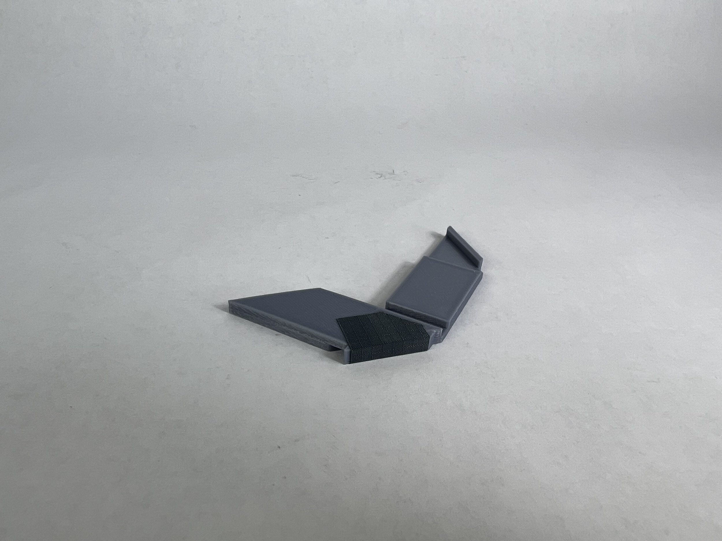
Figure 12
Above: Figure 13. Below: Figure 14
Figures 12-14. Add tape in these locations. There is also tape on the back side of Panels 3 and 4 not shown in this image.
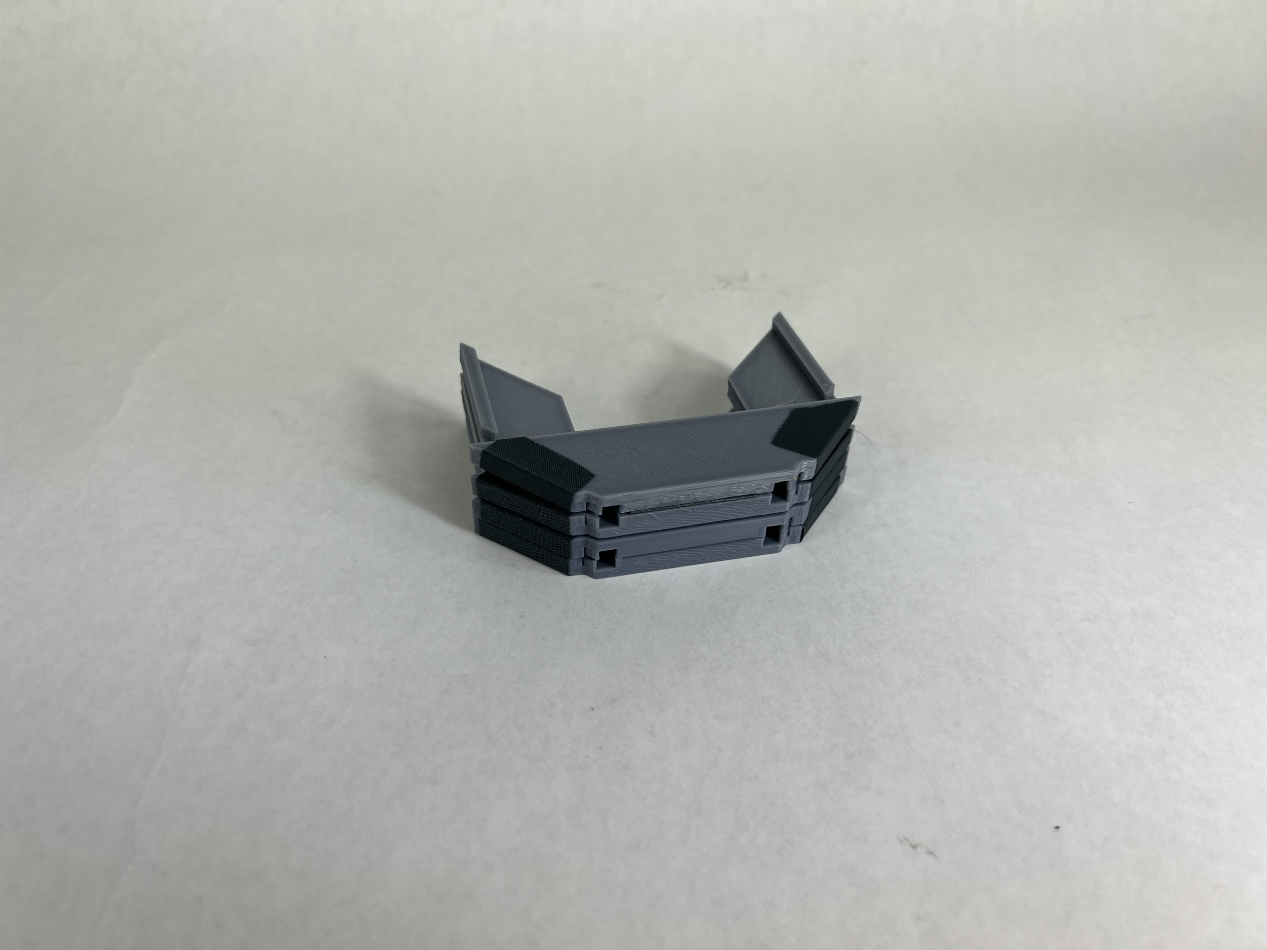
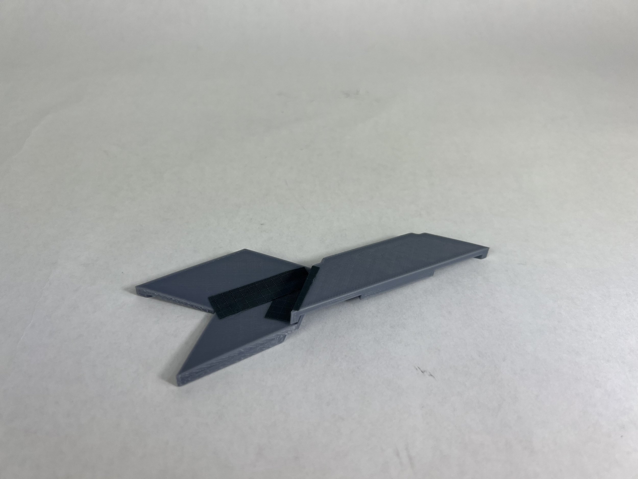
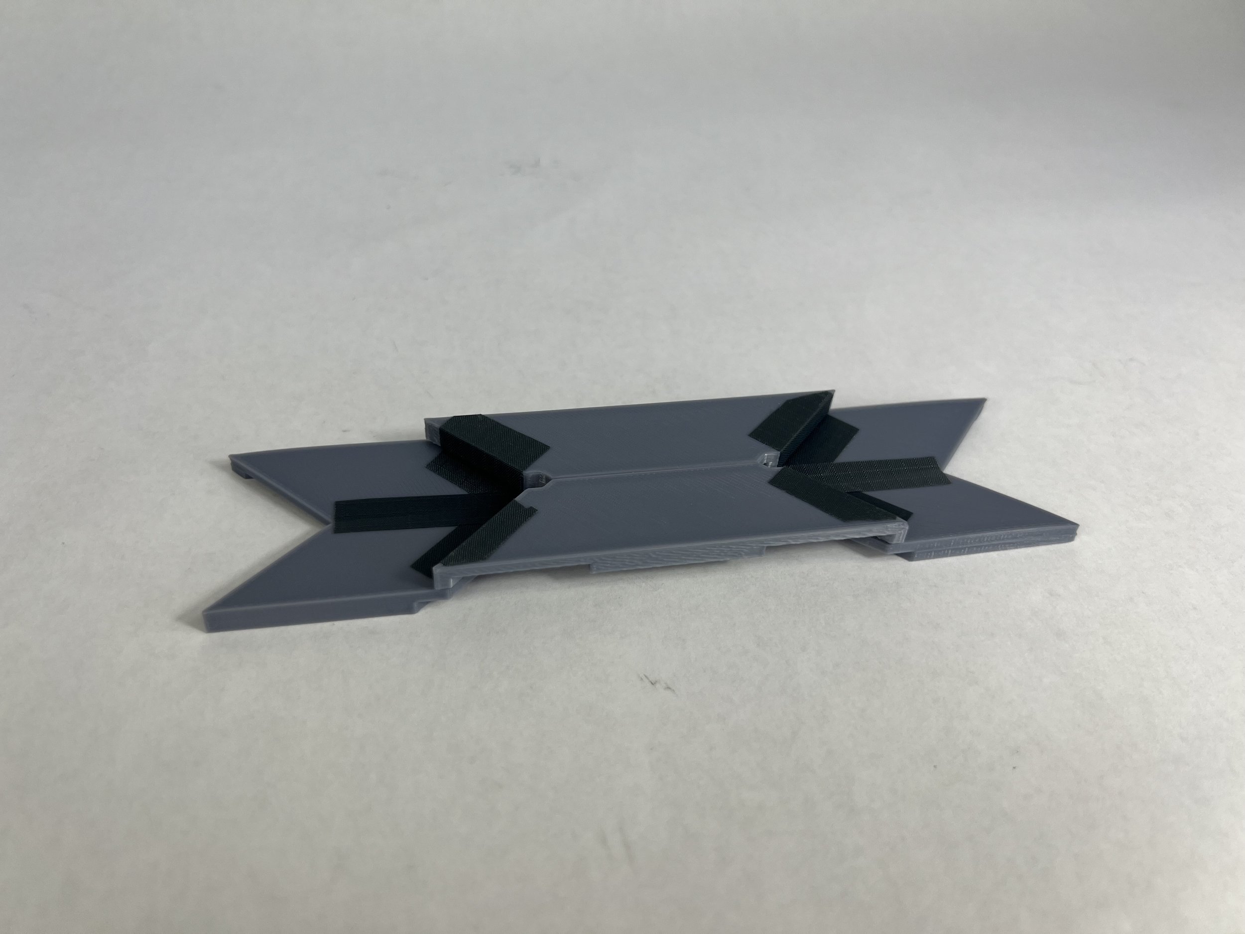
Figure 15
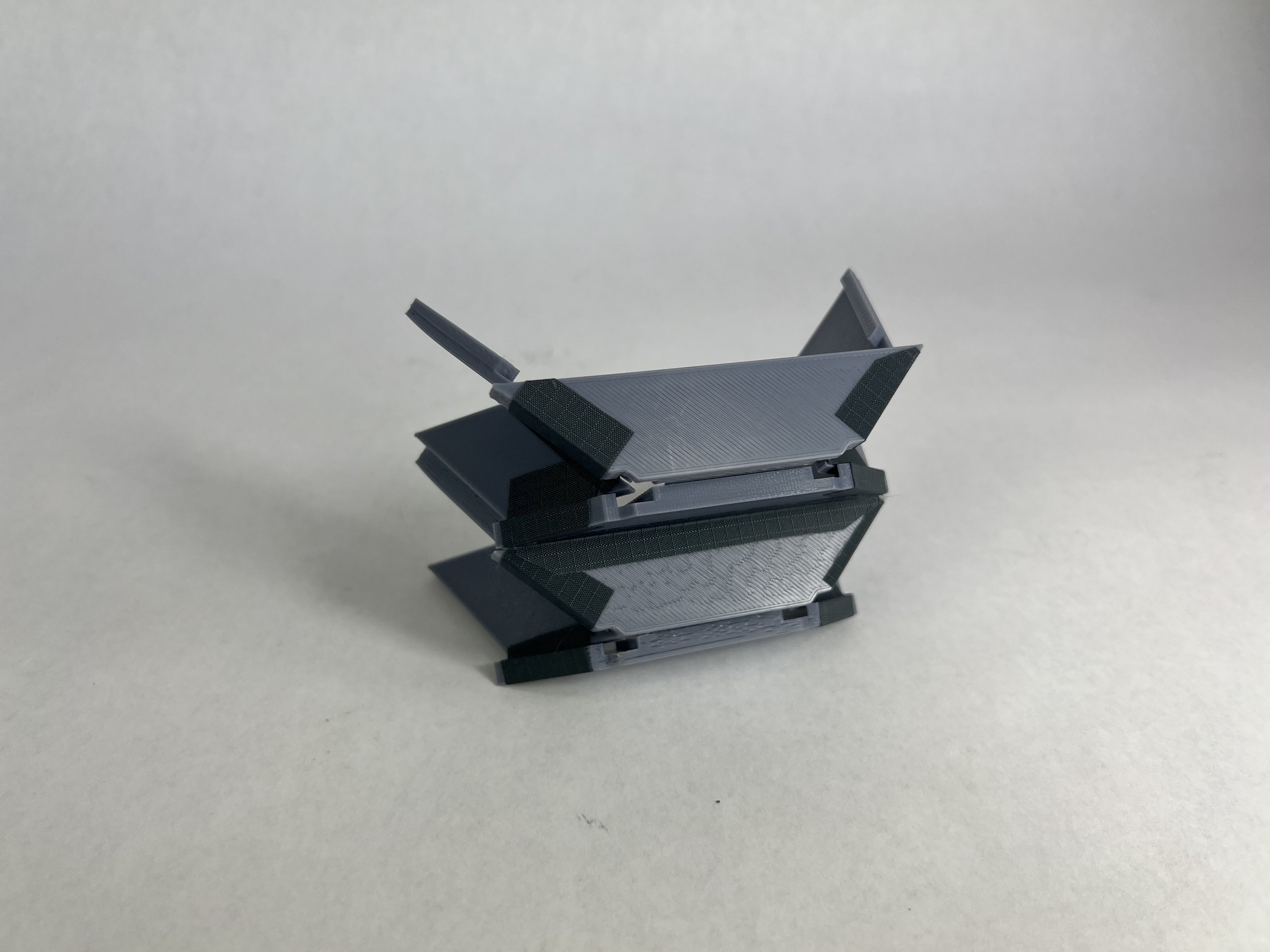
Above: Figure 16. Below: Figure 17
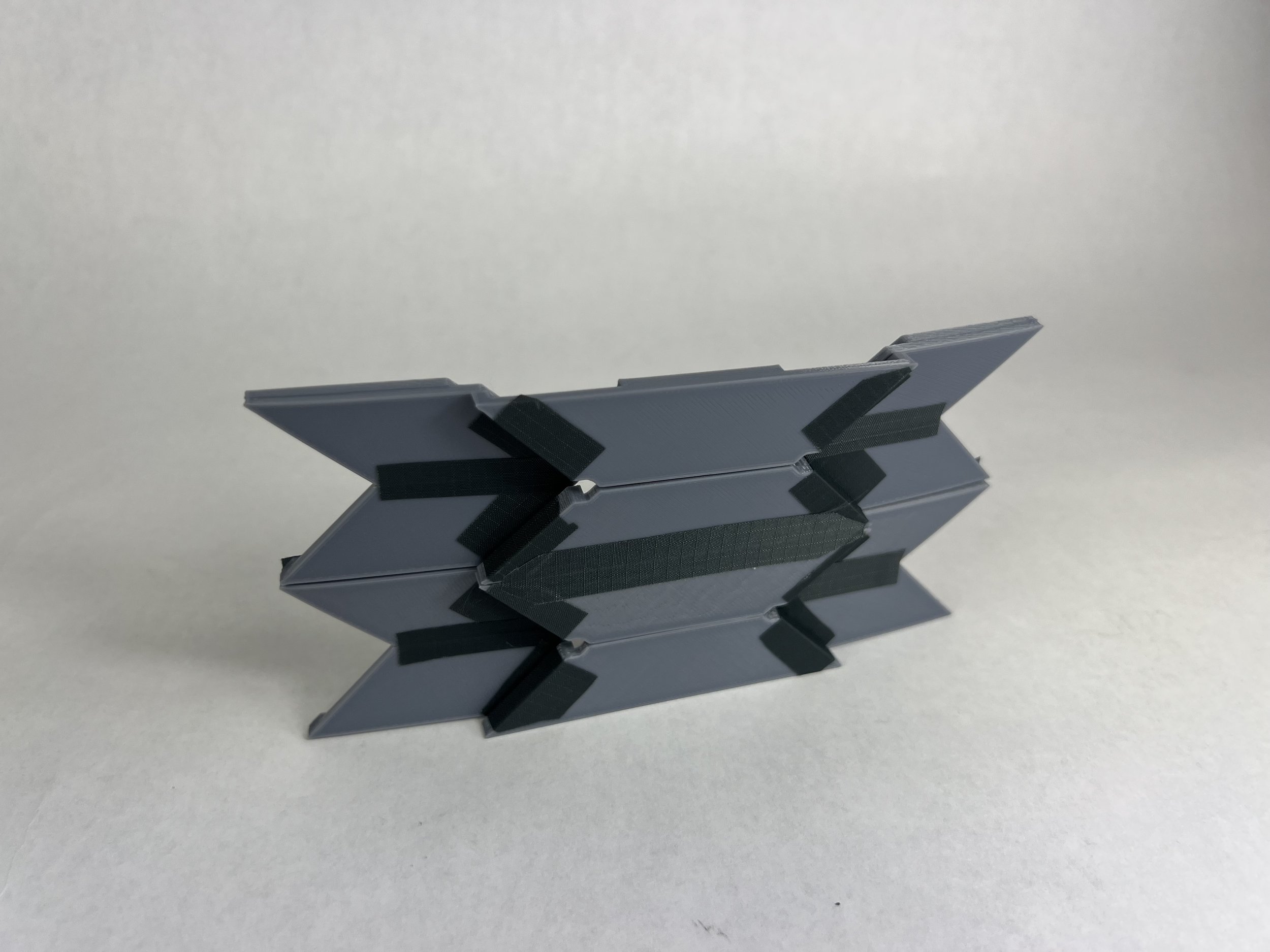
Figures 15-17. The finished product, closed, partially open, and fully open.
As an additional help, you can download some of the STL files I used in the creation of this prototype here. If you’re interested in additional origami-based designs that you can 3D print, check out the BYU Compliant Mechanisms Research Group’s Thingiverse account here. Our research group has uploaded a variety of origami inspired 3D prints that you can study and use as you become an origami designer.
Conclusion
In the end, there can be no tutorial that works for every pattern and every thickness accommodation technique, and that is one of the reasons why designing with origami can be so difficult. But the general rules remain the same: select a pattern, apply a thickness accommodation, choose hinges, and assemble.
You may come across challenges when trying to apply a different thickness accommodation or using a different pattern. Solutions to some of these problems can be as simple as removing some extra material, or they may be more difficult. Reference [3] is a good starting point for those who would like to dive deeper into understanding thick origami and specifically thickness accommodation techniques. When challenges do show up, don’t give up! With a little bit of extra effort you can figure it out. And hey, maybe you’ll even create a new thickness accommodation technique. Happy origami-ing!
Acknowledgements
I acknowledge the SolidWorks student license used to create these models. Thank you to Dr. Larry Howell, Dr. Collin Ynchausti, and other members of the compliant mechanisms lab for their support.
References
[1] Bolaños, D., Ynchausti, C., and Magleby, S. P.. “A Preliminary Approach To Select An Origami Source Pattern For Deployable Space Arrays.” ASME IDETC Conference Proceedings, St. Louis, Missouri, 2022.
[2] Tachi, Tomohiro & Miura, K.. (2012). Rigid-foldable cylinders and cells. Journal of the International Association for Shell and Spatial Structures. 53. 217-226.
[3] Lang, R. J., Tolman, K. A., Crampton, E. B., Magleby, S. P., and Howell, L. L., 2018, “A Review of Thickness-Accommodation Techniques in Origami-Inspired Engineering,” ASME Appl. Mech. Rev., 70(1), p. 010805.
To cite this article:
Roubicek, Clark. “Beyond Paper: How to Make Origami Out of Thick Materials.” The BYU Design Review, 29 May. 2023, https://www.designreview.byu.edu/collections/beyond-paper-how-to-make-origami-out-of-thick-materials.